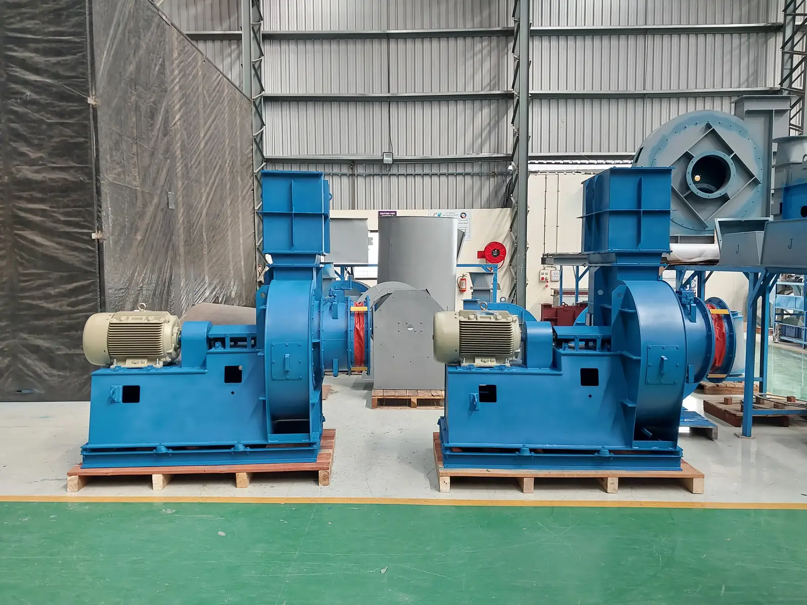
Nine times out of ten the fan is doing exactly what it was bought to do and the system is not what was quoted. System effect - a bend or a damper too close to the inlet or outlet, an abrupt transition, a spinning inlet - robs the fan of pressure the test rig gave it, and the fan then sits at a different point on its own curve. Measure the actual static at the fan flanges before you conclude the fan is short.
Low flow, weak suction, static pressure below design. It is the most common airflow complaint we see — dust collection, scrubber duty, foundry and furnace exhaust, food processing, paint-shop ventilation — and in most cases we investigate, the fan is delivering what its test report says it will. The shortfall sits in the system, in the measurement, or in a mechanical fault that has quietly bled off output. This is the diagnostic order we use in the field.
Ranked by how often it turns out to be the answer:
A fan leaves works run-tested against its performance report, so the higher prior sits with what happened after that: transport, installation, commissioning, operation, wear, or a bought-out component. That is where the evidence usually lands — check it in that order because it is efficient, not because anyone is being defended.
Safety first. Isolate and lock out the drive. Confirm zero energy before opening a guard, entering a duct, or touching a coupling. Fans coast a long time on good bearings.
1. Pull the performance test report before anything else. Fans are tested to IS 4894 / ISO 5801 / AMCA 210 method on a test bed. Read the design-condition column, not the test-condition column — density, temperature and speed differ between the two. More than one "failure" has turned out to be a fan achieving 312 mmWC at design conditions against 305 mmWC required, read off the wrong column. If the fan met its curve at works, the fault is almost certainly system-side.
2. Fix the measurement before you trust it. Take static pressure at the correct tapping — the transition piece — with a digital manometer. Do not accept an anemometer traverse as primary evidence: in a disturbed duct section it gives misleading results and it is not traceable to the test standard. Confirm you are reading static, not total.
3. Confirm rotation and speed — do this first on any flow shortfall, whatever the ammeter reads. Check impeller rotation against the casing arrow, and confirm the direction air actually leaves the outlet; those two together are the definitive check. A reversed centrifugal wheel still discharges the right way, so it looks like it is working — but on the backward-curved and radial wheels we build it meets the system resistance the wrong way and delivers only 40 to 50% of design flow at higher-than-normal current. Then tacho the actual RPM against the design and the pulley calculation — a wrong pulley or a slack belt drops flow and pressure together.
4. Map the installed system. Photograph or sketch inlet, outlet, every bend, every duct diameter, and the measurement point. Look for close-coupled elbows, mitred bends, sudden expansions, inlet obstructions. This is system effect — the fan is de-rated by flow distortion it was never sized for, and no work on the fan fixes it.
5. Walk the resistance path. Damper position (including isolation dampers left part-shut), filter or bag differential, choked hoods, collapsed bellows, duct leakage. Sum the installed static and compare with design. This is where the missing pressure usually is.
6. Only then open the fan. Impeller-hub-to-shaft clearance, impeller build-up and erosion, inlet-cone-to-shroud gap, coupling pin-and-bush condition, bearings. A worn or eccentric impeller and a hub walking on the shaft both cut output and raise vibration.
Transport & handling — impeller knocked out of balance, or hub disturbed, in transit. Shifted balance gives vibration plus reduced effective output. Confirm with an in-situ vibration reading and a hub-clearance check.
Installation — system effect from close-coupled bends and missing straight runs: distorted inlet flow raises effective resistance and de-rates the fan. Installed resistance above design from extra duct, added bends or undersized duct: the fan rides left on its curve — low flow, low amps. Confirm by summing installed static against design and checking duct geometry against straight-length guidance.
Commissioning — total pressure read instead of static, or an anemometer used in a disturbed section, producing an apparent shortfall on a healthy fan. Drive set-up error: wrong pulley ratio, slack belt, reversed rotation. Confirm at the transition piece, with a tacho, and against the casing arrow.
Operation & process — throttled damper or part-shut isolation, choked hood or filter (confirm damper position and filter ΔP); duct or flexible-joint leakage and collapsed bellows (confirm by walk-down and smoke/leak check). Or the duty was under-specified at order stage and the process simply needs more than was bought — confirm by comparing process demand with ordered duty. That is a re-rate question, not a fault.
Maintenance & wear — coupling pin-and-bush and bearing wear: driveline slop gives noise, lost transmitted power, vibration. On a 30 HP steel-plant exhaust fan, damaged coupling rubbers took both bearings with them after a restart. Impeller build-up, erosion or lining damage changes the blade profile and costs efficiency; on a 100 HP / 85,000 CMH scrubber fan a liberated impeller took the pillow block, bearing, belt, shaft and duct lining with it.
We service fans of any make, not only our own — on-site vibration diagnosis and balancing, bearing and coupling replacement, impeller repair, duct and system-effect assessment, and re-rating when the process has outgrown the fan. If the steps above have narrowed it to a mechanical fault or to a system that needs re-selecting, an engineer on site with a manometer, a tacho and a vibration meter will usually close it in one visit.
Contact: sales@jitamitrablowers.com · Jitamitra Help Desk +91 8329172325
Jitamitra Electro Engineering Private Limited. Quality management system ISO 9001:2015 certified. Fan performance tested to IS 4894 / ISO 5801 / AMCA 210 method. CE marking and ATEX (Zone 2/22) construction self-declared.
— Jitamitra Electro Engineering · Technical Services
Engineered for Every Application.
Before anyone argues about the fan, work out what the measured current says the machine is actually doing. Two sums settle most shortfall claims on site.
At a fixed volume flow, duct velocity rises as the square of the diameter reduction and friction loss rises as the square of velocity — so loss varies roughly as the fifth power of diameter. In practice:
That is why a duct run "value-engineered" one size smaller on site turns a comfortable selection into a fan that cannot make its duty — and why the first thing to check is the installed ductwork, not the wheel.
A 40 HP, 415 V motor measured at 38 A against roughly 52–55 A full-load: about 70 per cent of rated load. The fan is not overloaded, it is underloaded — it is not delivering design flow because the installed resistance is higher than the selection assumed, or the inlet is being strangled. Raising the overload setting fixes nothing here; it removes the only instrument that was telling you the truth.
Flow, static, gas temperature, application — or attach a spec, GA drawing or a multi-fan schedule. Engineer to engineer.
ISO 9001:2015 quality system · performance-tested to IS 4894 / ISO 5801 / AMCA 210 method · witnessed FAT on request.
*For our standard range. ATEX and special projects need 5 to 7 working days.
This site sets no cookies of its own. Google Analytics loads only if you accept. It sets two cookies, so we can see which fan topics people actually read. Decline and no analytics loads — the site works exactly the same. What we collect →