Matched set of boiler draught fans — ID, FD, PA and SA — on the Jitamitra shop floor
Home  /  Applications  /  Boiler fan suite (ID/FD/PA/SA)
Applications

The boiler fan suite — one matched set, one vendor, one QA record.

A boiler runs on four coordinated fans, not one. The ID fan pulls flue gas out to the stack, the FD fan pushes combustion air in, the PA fan dries and transports the fuel, and the SA / overfire-air fan stages the burn — and they must hold balanced draft together across every load. Buy them from four vendors and you inherit four GA languages, four spare kits and four people to blame when the furnace hunts. We supply the whole draught-fan island as one matched aerodynamic set — single GA drawing language, single QA record, single point of accountability — with each fan engineered across the envelope below: per fan up to 2,00,000 CMH, 2,000 mmWC, 400 HP and 600 °C.

4-in-1ID · FD · PA · SA set
2,00,000CMH max flow per fan
600 °CID gas temperature
400 HPdrive power per fan
15,000+
fans built since 2011
200 HP
VFD test rig · IS 4894 / AMCA 210
99%
on-time delivery
3
working days to quote — always
ID PULLS OUT · FD PUSHES IN · PA TRANSPORTS FUEL · SA STAGES THE BURN · ONE BALANCED SET
What it does

Four fans, one boiler — and they only work if they work together.

The boiler draught-fan island is a designed set, not four separate purchases: the ID and FD fans hold the furnace at target draft, while the PA and SA fans deliver and stage the combustion air. Supplied as one matched set, they share aerodynamic language, control logic, spares and a single QA record — so the boiler is commissioned against one drawing set, not reconciled across four.

  • 01
    Draught balance

    The ID and FD fans hold the furnace at target draft together — typically −5 to −10 mmWC at the boiler outlet. Track them as a pair across load and the furnace pressure stays steady; treat them as separate buys and it hunts.

  • 02
    Combustion air

    The FD, PA and SA fans deliver staged air for a clean burn — FD pushes the bulk combustion air, PA dries and transports the milled fuel at 1,000–1,800 mmWC, and SA / overfire-air stages the rest for low-NOx firing.

  • 03
    One set, one vendor

    One matched aerodynamic family, one GA drawing language, one coordinated control strategy and a single shared spares kit — 4 fans on 1 QA record instead of four suppliers and four sets of bearings, seals and interfaces.

INDUCED-DRAFT CENTRIFUGAL FAN Single-width single-inlet — scroll cut away to reveal the impeller inlet expansion joint MOTOR IE3 / VFD GAS IN GAS OUT n 1 2 3 4 5 6 7 8 9 10 1 Inlet cone (bell-mouth) 2 Backward-curved / radial-tipped impeller 3 Spiral volute casing 4 Replaceable AR wear plates (volute throat) 5 Shaft 6 Plummer-block bearings (L10 ≥ 40,000 h) 7 Shaft cooling disc (>400 °C duty) 8 Pedestal / base frame 9 Drive — motor + coupling 10 Outlet flange + duct take-off
Fig. 1The boiler draught-fan island — ID, FD, PA and SA centrifugal fans shown against a balanced-draft boiler, with the gas and air paths keyed below the drawing.
Why it is hard

Three things decide whether the set runs as one island or four arguments.

A boiler fails at the interfaces, not the fans. When ID and FD are supplied separately they do not track each other across load, so the furnace pressure hunts and the boiler trips on draft. When every fan turns down on its own logic, the set cannot hold a clean burn from 40% to 100% MCR. And when four vendors each ship their own QA record and spares, a single bearing failure becomes a 4-way argument about whose fan is at fault. Coordinate the set at design, and one vendor owns the whole island.

01 — BALANCE

Balanced-draft coordination

The ID and FD fans must track each other across every load, or the furnace pressure hunts — the ID over-pulls, the FD chases it, and the boiler trips on high or low furnace draft. Supplied by two vendors on two curves, they were never matched to hold −5 to −10 mmWC together.

How we engineer it out

We size the ID and FD curves as a coordinated pair off the same firing rate, with a common turndown map and matched control response, so furnace draft holds steady across the load range instead of oscillating.

02 — TURNDOWN

Matched turndown across the set

A boiler swings from 40% to 100% MCR. If each fan holds its duty on different logic, the air/fuel ratio drifts at part-load and the burn goes dirty — smoke, CO or unburnt carbon.

How we engineer it out

All four fans are sized to hold their duty from ~40% to 100% MCR on a common VFD-led control strategy, with each duty point engineered onto the stable region of its own curve.

03 — ACCOUNTABILITY

Single-vendor accountability

Four vendors means four GA languages, four spare kits, four sets of bearings and seals, and — when the furnace hunts or a fan trips — four suppliers each pointing at the others. Nobody owns the island.

How we engineer it out

One matched set on a single QA record, one GA drawing language, one shared spares and interface standard, and one point of accountability for the whole draught-fan island — not 4.

How we design for it

Every fan in the set is documented on the GA drawings you sign off — before we cut metal.

We don't bundle four catalogue near-fits. Each fan is engineered to its own position — ID to hot dirty gas, FD to efficient clean air, PA to fuel transport, SA to staged flow — then matched across the set on control, spares and documentation.

  • Family selection per position — The dirty ID fan on a rugged radial-tipped backward-curved wheel with wear protection for flue gas to 600 °C; the clean FD, SA and low-pressure air fans on efficient backward-curved-plate or airfoil wheels for high static efficiency; the high-pressure PA fan on a stiffened high-pressure casing holding 1,000–1,800 mmWC.
  • One control strategy across the set — A common VFD-led control strategy so ID and FD track for balanced draft and all four fans turn down together from ~40% to 100% MCR — VFD is our default; Inlet Guide Vanes (IGV) or inlet dampers remain available for legacy retrofit.
  • Shared spares, bearings and interfaces — The set is standardised on a common bearing, seal and coupling family and a shared spares kit wherever the duty allows — one L10h ≥ 40,000 h bearing standard, common Flexible Connection / Expansion Joint interfaces, and matched Isolation / Shut-off Damper scope — so one store serves four fans.
  • One documentation & QA package — A single GA drawing language, one QA and inspection record, and one performance-test dossier for the whole island — every fan proven on the 200 HP VFD test rig and balanced to ISO 21940 G6.3 (G2.5 / G1.0 on application) before dispatch.
Engineered to your duty point

We size each fan on the stable side of its own curve — and coordinate the set on one control map.

No catalogue fans bundled onto your boiler. Each of the four duty points is engineered onto the stable, best-efficiency region of its own selected wheel, then the ID and FD curves are matched as a coordinated pair for balanced draft — and every fan is verified on the 200 HP VFD test rig before dispatch, with the set tested against a common turndown map.

avoid: unstable 0 40,000 80,000 1,20,000 1,60,000 2,00,000 VOLUME FLOW RATE  [ CMH ] 0 500 1000 1500 2000 STATIC PRESSURE  [ mmWC ] 0 25 50 75 100 STATIC EFFICIENCY  [ % ] Fan static pressure System resistance Static efficiency BEP 82% DUTY POINT 1,20,000 CMH · 450 mmWC Fan static pressure System resistance Static efficiency
Fig. 2Representative characteristics for the four fans of the set — fan static pressure, system resistance and static efficiency vs. flow, each duty point engineered onto its stable region and the ID/FD pair matched for draft. Illustrative; every fan is sized to its own duty.
Capability envelope — Boiler fan suite

What we can supply, and where it stretches on application.

ParameterStandardOn application
Volume flow (per fan)up to 2,00,000 CMHhigher on enquiry; ID and SA typically carry the largest flow
Static pressure (per fan)up to 2,000 mmWCPA carries the highest static, typically 1,000–1,800 mmWC
FD / SA inlet air temperatureambient to 350 °C (APH-preheated air)higher on application with special metallurgy
ID gas temperatureup to 600 °C continuoushigher with refractory lining + special metallurgy
PA inlet air temperature250–350 °C (mill drying air)per mill and fuel
Drive power (per fan)up to 400 HPhigher with custom motor sourcing
Control across the setVFD default, matched turndown ~40–100% MCRInlet Guide Vanes (IGV) / inlet damper on legacy retrofit
Balance qualityISO 21940 G6.3 every fanG2.5 / G1.0 on application

The envelope above is per fan — each of the four fans is engineered inside it, and the set as a whole is coordinated on one control map. The ID fan carries the hot, dust-laden, potentially acid-condensate duty (to 600 °C); the FD and SA fans handle clean ambient-to-preheated air (to 350 °C); the PA fan carries the highest static (1,000–1,800 mmWC) with a fuel-laden discharge. Bearing life is a shared design target of L10h ≥ 40,000 h continuous across the set, with longer L10 on application. For a fuller treatment of any single position, see the individual ID, FD, PA and SA duty pages.

How a Jitamitra BOIL fan is specified

Specified, not picked from a shelf.

The same engineering language carries across all four fans — from your enquiry to the GA drawings to the nameplates — expressed in the standard AMCA conventions, so the set reads as one island.

Specification fieldOptions
Set compositionID (induced draft) + FD (forced draft) + PA (primary / mill air) + SA / overfire-air — supplied and coordinated as one matched set, sized off a single firing rate.
Arrangement (AMCA 99)Arr. 1 (overhung, fan bearings) / Arr. 4 (direct, motor on base) / Arr. 8 (overhung on common base) / Arr. 9 (overhung, motor side) / Arr. 10 (overhung, motor inside base) — selected per position by drive, access and temperature.
Width / inletSWSI (single width, single inlet) default across the set; DWDI (double width, double inlet) on the ID or SA fan where high flow at moderate pressure calls for it.
Wheel type (per position)ID — radial-tipped backward-curved (or straight-radial where fly-ash buildup dominates); FD / SA — backward-curved-plate or airfoil-bladed for efficiency; PA — backward-curved high-efficiency on a high-pressure casing.
Materials of constructionID — IS 2062 casing with AR wear plates, hard-faced wheel, 316L / Corten for acid dew-point; FD / SA — mild steel + epoxy, stainless for humid or corrosive air; PA — IS 2062 stiffened casing, hard-faced leading edges for the fuel stream.
Drive & controlDirect-coupled / V-belt / VFD (default across the set for coordinated turndown). Drive up to 400 HP per fan; speed typically 600–1,800 RPM; ID and FD matched as a control pair for balanced draft.
Spark-resistant / ATEX scopeSpark-Resistant Construction and ATEX Zone 2/22 self-declaration (Category 3, per 2014/34/EU) on the PA fan for combustible biomass or high-volatile-coal dust — aluminium impeller, bonded earthing, controlled tip clearance — where the area classification calls for it.
Accessories & shared scopeInlet Guide Vanes (IGV) or Discharge / Outlet Damper; Isolation / Shut-off Damper; Flexible Connection / Expansion Joint; Inlet / Discharge Silencer on the FD and SA fans; Impeller Wear Protection and Heat Slinger / cooling disc on the ID and PA fans; VFD package and a single shared spares kit across the set.
The proof, not the promise

We test before we ship — and you're welcome to witness it.

Every job's performance is verified at our works on the 200 HP VFD test rig, to the AMCA 210 / ISO 5801 method, before dispatch.

  • Customer-witnessed FAT on request — at no extra cost
  • Rotors balanced to ISO 21940 G6.3 as standard (G2.5 / G1.0 on application) before they leave the floor
  • Full NDT in-house — DP, MPI, UT, RT — to what the duty demands
30+ INDUSTRIES · 45 APPLICATION / DUTY TYPES
Where the suite runs

One matched set on every kind of boiler island.

Thermal Power

Utility and cogen boiler islands — full ID/FD/PA/SA set on pulverised-fuel and CFBC units.

Sugar & Distilleries

Bagasse-fired boiler draught sets for co-gen and process steam.

Pulp & Paper

Recovery and power-boiler ID/FD/PA/SA sets for mill steam and power.

Chemicals & Petrochem

Captive process-boiler draught sets for steam and utility.

Food Processing

Process-steam boiler fan sets for drying, evaporation and sterilisation.

Cement

Captive-power boiler draught sets on the plant's own generation island.

Textile

Process-steam boiler ID/FD sets for dyeing, finishing and captive power.

Your process

45 application/duty types engineered. Tell us yours.

Standards & conformity

Stated precisely — because procurement checks.

What our marks mean, in the words that survive an audit.

Performance

Tested to the AMCA 210 / ISO 5801 method, in-house on our 200 HP VFD rig. Tested-to-method — not AMCA-certified.

Quality system

ISO 9001:2015 — third-party certified. Our only third-party certification.

CE conformity

Self-declared per 2006/42/EC + 2014/35/EU (Module A). A self-declaration, not a notified-body certificate.

ATEX conformity

Self-declared, Zone 2/22, Category 3, per 2014/34/EU, where the area classification calls for it.

Oil & gas duty

Designed and built to API 673 as project-specific scope.

Welding

ASME Sec IX qualified welders + WPS for every joint.

Balance

ISO 21940 — G6.3 minimum, G2.5 / G1.0 on application.

Vibration

ISO 20816 evaluation; ISO 14694 for fan-specific limits.

Lead time & process

From enquiry to a tested fan on your dock.

StageStandard dutyAPI-673 / engineered
Offer / quotation3 working days — always7–10 working days
GA drawing for approval2–3 weeks from PO3–4 weeks from PO
Manufacture + balance + paint6–10 weeks10–14 weeks
Performance test + witnessed FAT~1 week1–2 weeks
Order-to-dispatch (total)9–14 weeks14–20 weeks

Shutdown-driven replacements: we have shipped fans within 6 weeks of a clean PO. Tell us your shutdown window and we commit to a dated plan.

Questions engineers ask

The eight we hear most before a PO.

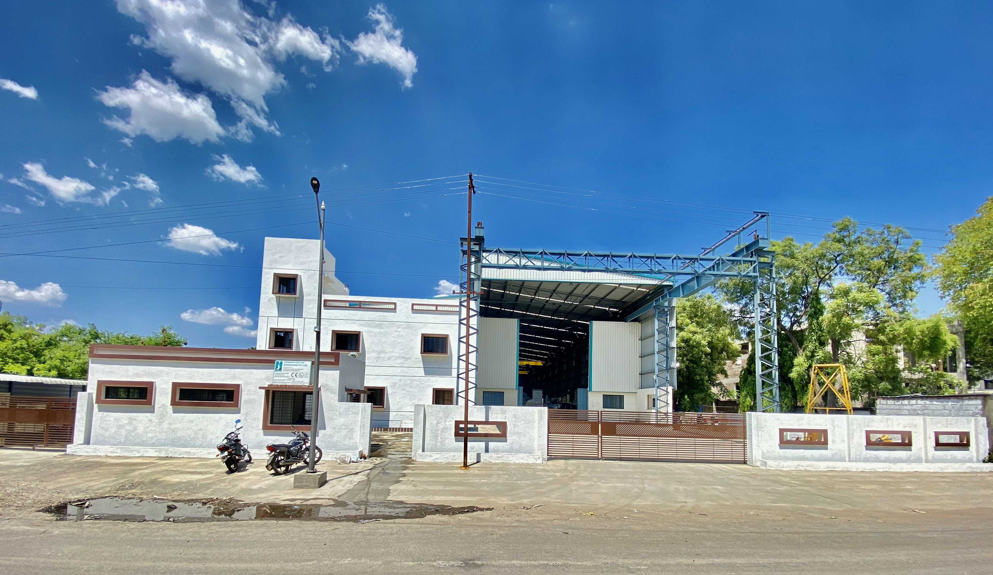
Why buy the whole boiler fan set from one vendor instead of four?
Because a boiler fails at the interfaces, not the fans. When you buy the ID, FD, PA and SA fans from four vendors you inherit four GA drawing languages, four spare kits, four sets of bearings and seals, and — when the furnace hunts or a fan trips — four suppliers each pointing at the others. Supplied as one matched set, the fans share one aerodynamic language, one coordinated control strategy, one QA record and one spares kit, so the boiler is commissioned against a single drawing set and one vendor owns the whole draught-fan island. That is the point of the suite: one set, one vendor, not four arguments.
How do you coordinate the ID and FD fans for balanced draft?
The ID and FD fans have to track each other across every load or the furnace pressure hunts — the ID over-pulls, the FD chases it, and the boiler trips on furnace draft. We size the ID and FD curves as a coordinated pair off the same firing rate, with a common turndown map and matched control response, so the furnace holds target draft, typically -5 to -10 mmWC, steady across the range instead of oscillating. Buying them separately is exactly what makes balanced draft hard; matching them at design is what makes it hold.
Can the whole set turn down together across boiler load?
Yes. A boiler swings from roughly 40% to 100% MCR, and if each fan turns down on its own logic the air/fuel ratio drifts at part-load and the burn goes dirty. We size all four fans to hold their duty from about 40% to 100% MCR on a common VFD-led control strategy, with each duty point engineered onto the stable region of its own curve. VFD is our default because speed control avoids the throttling loss of a damper at part-load; Inlet Guide Vanes or inlet dampers remain available for legacy retrofit.
What is the ID fan's job in the set, and how is it different?
The ID fan sits downstream of the boiler and pulls hot flue gas out, holding the furnace under negative pressure and pushing the gas through the pollution-control train to the stack. It carries the harshest duty of the four: flue gas up to 600 °C, fly ash, and sometimes acid dew-point condensate, so it gets a rugged radial-tipped backward-curved wheel, wear protection and corrosion-resistant metallurgy. The individual Induced Draft (ID) page covers that duty in full.
What is the difference between the FD, PA and SA fans?
The FD fan pushes the bulk of the combustion air into the furnace at positive pressure on the clean, efficient side of the process. The PA fan carries the highest static, typically 1,000 to 1,800 mmWC, to dry the milled fuel and transport it from the pulveriser to the burner, with a combustible fuel-laden discharge. The SA or overfire-air fan supplies and stages the remaining combustion air for a clean, low-NOx burn. Each is engineered to its own regime, then matched across the set on control and spares. The individual FD, PA and SA pages cover each duty in full.
Do all four fans share the same spares, bearings and interfaces?
Wherever the duty allows, yes. We standardise the set on a common bearing, seal and coupling family, a shared spares kit, and common Flexible Connection / Expansion Joint and Isolation / Shut-off Damper interfaces, all built to one L10h design target of at least 40,000 hours continuous. That means one store serves four fans instead of four separate spare inventories. Where a position demands something specific — hard-faced wear parts on the ID and PA wheels, for instance — that is called out on the GA, but the common kit stays common.
Can you supply just part of the set, or match fans we already have?
Yes. The suite is the single-source offer, but a credible single source names its own boundaries: if you already run a serviceable FD fan and only need the ID, PA and SA replaced, we engineer the new fans to match the existing duty point, bearing centres and orientation of the one you keep, so the set still reads as one island. Send the old GA, nameplate and a curve if you have one and we match to it, rather than forcing a nearest-catalogue substitute.
Are the fans built to AMCA, CE, ATEX and ISO requirements?
Every fan in the set is performance-tested in-house to the AMCA 210 / ISO 5801 method on our 200 HP VFD test rig, and balanced to ISO 21940 G6.3 as standard (G2.5 / G1.0 on application) — that is our in-house test method, not an AMCA certification. CE is self-declared per 2006/42/EC and 2014/35/EU, and ATEX Zone 2/22 is self-declared per 2014/34/EU (Category 3), typically on the PA fan where combustible dust and the area classification call for it. To be precise: those are self-declarations of conformity, not third-party certifications. Our only third-party certification is ISO 9001:2015.
Across the range

Where the boiler fan suite fits — the fans in the set, related duties, and the industries served.

The same engineering, viewed three ways — by fan family, by duty, and by industry. Follow the cross-references.

Take it further

Specs an engineer can use — not a brochure.

Engineer to engineer

Send us the duty point.
We'll quote in 3 working days — always.

No model numbers needed. Give us the operating conditions — flow, static, gas temperature, composition, particulate, and any tender standard — and our application engineers size the fan and quote it. Attach a spec or GA if you have one.

+91 90110 09155  ·  mihir.jitamitra@gmail.com