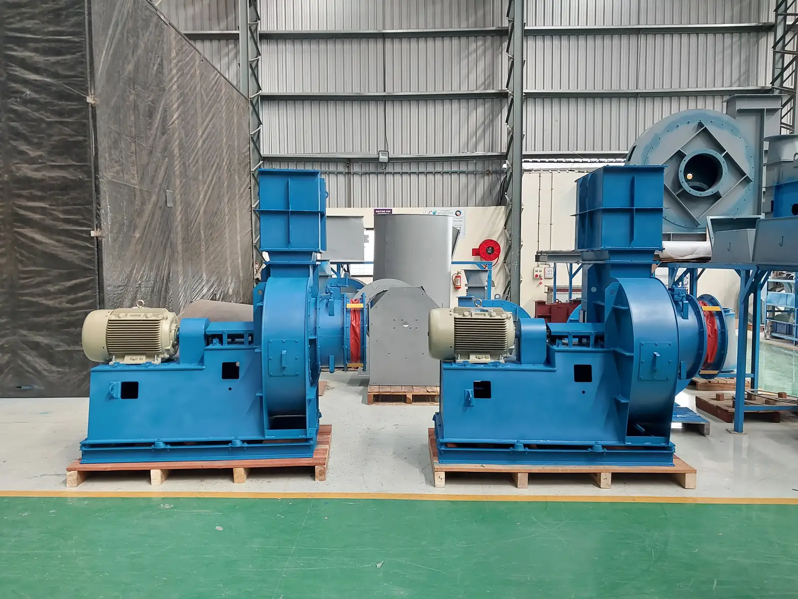
Two coupled-drive centrifugal fans on the Jitamitra shop floor
Home  /  Applications  /  Hot-gas (>300 °C) process
Applications

Hot gas fans — built for sustained 500 °C, engineered for what fails when metal expands.

When the gas is hot enough to anneal mild steel, ordinary fan engineering stops working. The shaft elongates and binds the bearings. The casing grows and cracks rigid joints. Bearing housings cook in their own conducted heat. We build hot-gas fans for kilns, furnaces, RTOs, heat-treatment lines, secondary steel-making and glass-melting — to the full 500 °C continuous ceiling, higher with refractory lining or transient pulses, across the envelope below.

2,25,000CMH max flow
2,000mmWC max static
500 °Ccontinuous gas
425 HPdrive power
15,000+
fans built since 2011
200 HP
VFD test rig · IS 4894 / AMCA 210
95%
on-time delivery (ERP statistics)
3
working days to quote
AT THE FURNACE OR KILN OUTLET · GAS HOT ENOUGH TO ANNEAL STEEL · METAL EXPANDING · HEAT CONDUCTING TO THE BEARINGS
Our executed range

Hot-gas (>300 °C) process — fans we've built

A sample of units we've engineered, built and dispatched — each to a customer's duty point. Customer names and identifying marks are withheld. Click any photo to enlarge.

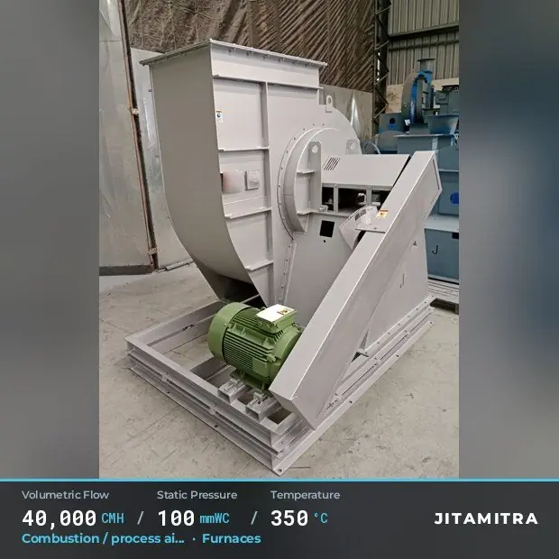
Jitamitra Furnaces fan — real dispatched build
Jitamitra Air Filtration & Pretreatment fan — real dispatched build
Jitamitra Pharmaceuticals fan — real dispatched build
Jitamitra Air Filtration & Pretreatment fan — real dispatched build
Jitamitra Sugar fan — real dispatched build

Browse our rich executed product range →

What changes at high temperature

Three physics changes dominate every hot-gas fan — and they all fight you at once.

On a hot-gas fan the duty point is the easy part. The real engineering is what happens to the metal at temperature: it loses strength, it grows, and it conducts heat into the bearings. Each of the three drives a different design choice.

  • 01
    Hold strength

    At 600 °C mild steel keeps only ~40% of its room-temperature yield. Blade thickness, geometry and speed must be sized so centrifugal stress at temperature — not at 20 °C — stays inside allowable limits.

  • 02
    Absorb growth

    A 1 m shaft elongates ~6 mm from cold to 500 °C; a 2 m casing grows ~12 mm. Bearings, foundation, ducting and access doors all have to take that movement without binding, cracking or leaking.

  • 03
    Shed heat

    Heat flux travels the shaft and casing into the bearing housings. Above 100 °C at the housing the lubricant breaks down and the bearing fails — so the design has to actively carry heat away from that zone.

Why it is hard

Three failure modes decide whether a hot-gas fan survives the first firing season.

High temperature attacks the rotating wheel, the static casing and the bearing end of the shaft in three different ways. Design for each, and the fan holds shape through repeated heat-up cycles. Design for the duty point alone, and it creeps, cracks or cooks within the first 12–24 months.

01 — CREEP

Impeller creep & distortion

Thin, efficient backward-curved blades lose strength and slowly creep out of shape above ~482 °C, throwing the rotor out of balance.

How we engineer it out

Wheel type shifts toward rugged radial blades and the max speed is derated; impeller metallurgy steps up the creep ladder — Cr-Mo (16Mo3, 2.25Cr-1Mo) or stabilized austenitic 304H / 321 / 347 by temperature band.

02 — OXIDATION

Casing scaling & joint cracking

Carbon steel reaches its oxidation limit at ~482–510 °C and the casing scales; rigid joints crack as the casing grows ~14 mm across a 2 m diameter.

How we engineer it out

Casing metallurgy follows its own oxidation ladder (Cr-Mo, austenitic 304 / 321, 310S, then refractory lining); fabric or metal expansion joints at inlet and outlet absorb the growth, and the foundation lets the casing slide without cracking the grout.

03 — HEAT SOAK

Bearing & shaft cook

Conducted heat raises the bearing housing past the lubricant rating; left unmanaged the shaft binds and the bearing seizes.

How we engineer it out

Bearings move outside the airstream above ~120 °C; air-cooled shaft and heat slinger from ~482 °C, water-cooled above ~1010 °C; water-cooled housing recommended above 200 °C.

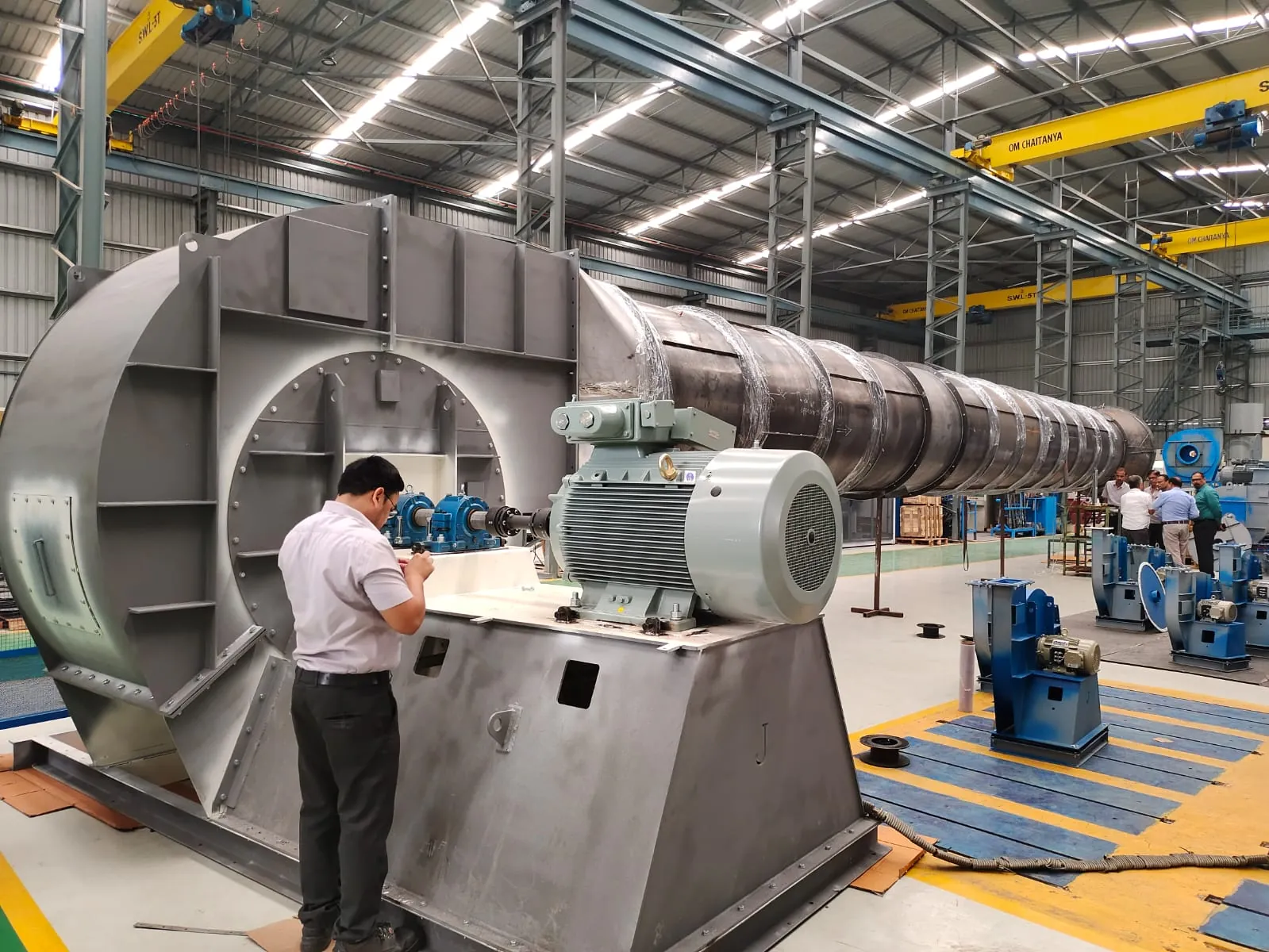
Jitamitra executed fan project
How we design for it

Every metallurgy and cooling choice is documented on the GA drawing you sign off — before we cut metal.

We don't sell a catalogue near-fit. The fan is engineered to your gas temperature — continuous and transient — its composition, particulate and operating point, with two separate material ladders for the wheel and the casing.

  • Two material ladders, not one — The rotating wheel is creep-limited and tops out below the static, oxidation-limited casing. We publish and quote them separately — impeller metallurgy on one line (MS → 16Mo3 / Cr-Mo → 304H / 321 / 347310S → Inconel above ~1050 °C), casing on another (carbon steel → Cr-Mo / austenitic → refractory-lined above ~870 °C).
  • Shaft cooling & bearing isolation — Bearings sit outside the airstream above ~120 °C; air-cooled shaft + heat slinger from ~482 °C to ~1010 °C, water-cooled shaft above that; shaft cooling disc standard above 350 °C; carbon-ring seal with nitrogen purge on the shaft penetration.
  • Thermal growth & expansion joints — Fabric or metal expansion joints at fan inlet and outlet, sized for the growth between cold and hot states — ~6 mm per metre of shaft at 500 °C. Anchor bolts arranged so the casing grows axially without cracking the grout; foundation drawings ship with the GA package.
  • Insulation, refractory & re-rate — Ceramic-fibre insulation and double-jacketed housing above ~537 °C; refractory lining available 600 °C+, standard on our highest-temperature builds — designed and offered to 700 °C, highest delivered to date 500 °C — with a ~50 °C/hour heat-up schedule. Performance re-rated for hot density — air at 300 °C is roughly half the density of 20 °C air.
Engineered to your duty point

We size the fan where its curve crosses your system at temperature — then prove it on the rig.

No catalogue fan forced onto your spec. Your operating point is engineered onto the best-efficiency region of the selected wheel and corrected for hot density — then verified on the 200 HP VFD test rig as a cold-air equivalent test, with hot-gas operation extrapolated by fan-law correction before dispatch.

avoid: unstable 0 40,000 80,000 1,20,000 1,60,000 2,00,000 VOLUME FLOW RATE  [ CMH ] 0 500 1000 1500 2000 STATIC PRESSURE  [ mmWC ] 0 25 50 75 100 STATIC EFFICIENCY  [ % ] Fan static pressure System resistance Static efficiency BEP DUTY POINT 1,20,000 CMH · 450 mmWC Fan static pressure System resistance Static efficiency
Fig. 2Representative hot-gas fan characteristic — fan static pressure, system resistance and static efficiency vs. flow, with the duty point engineered onto the best-efficiency region and re-rated for hot density. Illustrative; every fan is sized to its own duty.
Capability envelope — hot-gas service

What we can supply, and where it stretches on application.

ParameterStandardOn application
Volume flowup to 2,25,000 CMHhigher on enquiry
Static pressureup to 2,000 mmWChigher on enquiry
Continuous operating temperatureup to 500 °Chigher with refractory lining + special metallurgy
Drive powerup to 425 HPhigher with custom motor sourcing
Speed600–1,800 RPM typical, derated above ~482 °Cper duty + sound limits
Balance qualityISO 21940 G6.3G2.5 / G1.0 on application
Bearing life (design target)L10h ≥ 40,000 h continuouslonger L10 on application

The envelope above covers the great majority of industrial hot-gas duty. Refractory liner is available 600 °C+ and is standard on our highest-temperature builds — designed and offered to 700 °C, highest delivered to date 500 °C; the shaft-cooling disc is standard above 350 °C. For duty beyond 500 °C continuous we engineer to spec — stepping the wheel and casing up their separate material ladders — and quote on enquiry.

How a Jitamitra HT fan is specified

Specified, not picked from a shelf.

The same engineering language carries from your enquiry to the GA drawing to the nameplate — expressed in the standard AMCA conventions, with the wheel and casing metallurgy called out separately.

Specification fieldOptions
Arrangement (AMCA 99)Arr. 1 / 8 (overhung, fan bearings outside the airstream) and Arr. 9 default for hot-gas duty; Arr. 4 (wheel on motor shaft) only up to ~120 °C, or ~230 °C with a special motor — selected by drive, access and temperature.
Width / inletSWSI (single width, single inlet) default for hot-gas duty; DWDI (double width, double inlet) with an inlet box for high flow at moderate pressure.
Wheel typeBackward-curved / airfoil up to ~482 °C (high efficiency); radial / forward-curved above ~482 °C where thin blades would creep — rugged radial blades hold shape, with the max speed derated.
Class (by pressure / outlet velocity)Class I / II / III selected from the duty point on the pressure-vs-outlet-velocity limits; higher class = heavier construction for higher pressure and tip speed.
Materials — impeller (creep-limited)MS / IS 2062 to ~250 °C; low-alloy Cr-Mo / 16Mo3 to ~500 °C; austenitic 304H / 321 / 347 to ~650 °C; 309 / 310 / 310S to ~870 °C; Inconel above ~1050 °C.
Materials — casing (oxidation-limited)Carbon steel to its oxidation limit ~482–510 °C; Cr-Mo or austenitic 304 / 321 to ~650 °C; 310S to ~870 °C; refractory-lined steel casing above that — called out separately from the wheel.
DriveDirect-coupled / V-belt / VFD. Drive up to 425 HP across the envelope; speed typically 600–1,800 RPM, derated above ~482 °C.
Accessories & high-temp scopeFabric or metal expansion joints at inlet and outlet (growth ~6 mm/m of shaft at 500 °C); air- or water-cooled shaft + heat slinger; shaft cooling disc (standard above 350 °C); water-cooled bearing housing above 200 °C; carbon-ring seal with nitrogen purge; ceramic-fibre insulation / double-jacketed housing above ~537 °C; refractory lining and heat-up schedule; foundation drawings with the GA.
Jitamitra in-house capability
The proof, not the promise

We test before we ship — and you're welcome to witness it.

Every job's performance is verified at our works on the 200 HP VFD test rig, to the IS 4894 / ISO 5801 / AMCA 210 method, before dispatch.

  • Customer-witnessed FAT on request — at no extra cost
  • Rotors balanced to ISO 21940 G6.3 as standard (G2.5 / G1.0 on application) before they leave the floor
  • Full NDT in-house — DP, MPI, UT, RT — to what the duty demands
30+ INDUSTRIES · 45 APPLICATION / DUTY TYPES
Where our hot-gas fans run

Proven where the gas is hottest.

Iron & Steel

Reheating-furnace flue gas, electric-arc furnace dedusting (post-cooling), sinter-plant ID, ladle-metallurgy fume extraction.

Cement

Kiln main-burner exhaust (pre-ESP), pre-heater fans, calciner ID, kiln-hood ventilation.

Foundry, Casting & Forging

Cupola flue gas, induction-furnace fume, heat-treatment-furnace ID, forge-shop ventilation.

Glass

Float-glass furnace flue gas, oxygen-fuel-fired furnace exhaust, regenerator gas handling.

Chemicals & Petrochemicals

RTO hot-side fans, RCO recirculation, high-temperature process-boiler ID.

Pharmaceuticals

High-temperature solvent recovery and RTO fans for VOC abatement.

Mining & Minerals

Kiln duty for non-ferrous metal processing and fly-ash handling post-boiler.

Your process

45 application/duty types engineered. Tell us your gas temperature.

Standards & conformity

Stated precisely — because procurement checks.

What our marks mean, in the words that survive an audit.

Performance

Tested to the IS 4894 / ISO 5801 / AMCA 210 method, in-house on our 200 HP VFD rig. Tested-to-method — not AMCA-certified.

Quality system

ISO 9001:2015 — third-party certified. Our only third-party certification.

CE conformity

Self-declared per 2006/42/EC + 2014/35/EU. A self-declaration, not a notified-body certificate.

ATEX conformity

Self-declared, Zone 2/22, Category 3, per 2014/34/EU, where the area classification calls for it.

Oil & gas duty

Designed and built to API 673 as project-specific scope.

Welding

ASME Sec IX qualified welders + WPS for every joint.

Balance

ISO 21940 — G6.3 minimum, G2.5 / G1.0 on application.

Vibration

ISO 14694 fan-specific limits; ISO 20816 general evaluation method.

Lead time & process

From enquiry to a tested fan on your dock.

StageStandard dutyCE / ATEX / API / AMCA
Offer / quotation3 working days5 to 7 working days
GA drawing for approval3 days from customer PO5 to 7 days from customer PO
Manufacture + balance + paint2 to 3 weeks from PO + PI + approved GAD4 to 5 weeks from PO + PI + approved GAD
Performance test + witnessed FAT~1 week~1 week
Order-to-dispatch (total)4 to 6 weeks7 – 9 weeks

Shutdown-driven replacements: we have shipped fans within 3 weeks of a clean PO. Tell us your shutdown window and we commit to a dated plan.

Questions engineers ask

The eight we hear most before a PO.

What is the maximum gas temperature your hot-gas fans handle?
Continuous duty up to 500 °C across the envelope — our published ceiling. Above 500 °C continuous we engineer to spec with refractory lining and stepped-up metallurgy. The fan is built for your stated continuous temperature and your transient excursion case, not a generic rating, so tell us both.
What materials do you use at 400 and 500 °C?
We quote the wheel and the casing on two separate ladders because the rotating wheel is creep-limited and tops out below the oxidation-limited casing. Roughly: carbon steel / IS 2062 to ~250 °C; low-alloy Cr-Mo or 16Mo3 for highly stressed wheels to ~500 °C; austenitic 304H / 321 / 347 to ~650 °C; 309 / 310 / 310S to ~870 °C; Inconel above ~1050 °C. The casing follows carbon steel to ~482-510 °C, then Cr-Mo or austenitic, then 310S, then refractory lining. We size the exact grades to your gas temperature and composition.
How do you keep the bearings from overheating?
Three measures by temperature. Above ~120 °C the bearings move outside the airstream (Arrangement 1 / 2 / 8 / 9). Above 200 °C we recommend a water-cooled bearing housing. From ~482 °C an air-cooled shaft and heat slinger carry heat away from the bearing end, switching to a water-cooled shaft above ~1010 °C. A shaft cooling disc is standard above 350 °C. The target is to hold the bearing housing below the lubricant rating in continuous service.
How do you handle thermal expansion at temperature?
We size for the real growth. A 1 m shaft elongates about 6 mm from cold to 500 °C and a 2 m casing grows about 12 mm. Fabric or metal expansion joints at the fan inlet and outlet absorb that movement, anchor bolts are arranged so the casing grows axially without cracking the grout, and access doors and ducting connections are detailed to take the growth. Foundation drawings ship with the GA package.
When do I need a refractory-lined fan, and what does it add?
Refractory lining is available from 600 °C and is standard on our highest-temperature builds — we design and offer to 700 °C, and our highest delivered duty to date is 500 °C — on builds where metallic casing alone cannot hold the temperature. It is a static casing lining only — it cannot be applied to a rotating wheel, so above ~870 °C we specify the wheel metallurgy and the casing refractory as two separate lines on the offer. Refractory adds offer and build time and needs a pre-startup heat-up schedule, typically 50 °C per hour, to avoid thermal-shock cracking.
Is a hot-gas fan ATEX-classified?
Generally no. Hot-gas operation is usually above the auto-ignition temperature of most combustible dusts, so the dust either burns out upstream or never forms an explosive atmosphere, and the fan is typically not ATEX-classified. The exception is if the gas itself is a flammable vapour at risk of explosion, in which case we reclassify the duty and route it differently. We will tell you on enquiry.
Do you performance-test a hot-gas fan before dispatch?
Yes. Every fan is performance-tested in-house to the IS 4894 / ISO 5801 / AMCA 210 method on our 200 HP VFD test rig. Because the rig runs cold air, the test is a cold-air equivalent and hot-gas operation is extrapolated by fan-law correction for hot density — air at 300 °C is roughly half the density of 20 °C air. The fan is dynamically balanced to ISO 21940 G6.3 as standard (G2.5 / G1.0 on application), with ISO 20816 vibration checked at FAT cold and again at hot commissioning. Tests are customer-witnessed on request.
What is the lead time for a refractory-lined high-temperature fan?
Standard hot-gas duty runs about 14-20 weeks order-to-dispatch: offer 5-7 working days, design and GA 3-4 weeks from PO, manufacture, balance and paint 10-14 weeks, then cold performance test and FAT 1-2 weeks. A refractory-lined high-temperature build runs about 19-25 weeks, with the offer at 10-14 working days and refractory work added through manufacture. Site refractory commissioning and the initial firing add 1-2 weeks at site, customer-led with our engineering support.

Across the range

Where hot-gas fans fit — the fans that run them, related duties, and the industries served.

The same engineering, viewed three ways — by fan family, by duty, and by industry. Follow the cross-references.

Take it further

Specs an engineer can use — not a brochure.

A job like yours
Air that holds its static, build after build
Ready to quote?

Send us the duty point. We'll quote in 3 working days.*

Flow, static, gas temperature, application — or attach a spec, GA drawing or a multi-fan schedule. Engineer to engineer.

Get a quote → Email the desk

ISO 9001:2015 quality system · performance-tested to IS 4894 / ISO 5801 / AMCA 210 method · witnessed FAT on request, at no cost.

*For our standard range, additional days required for special projects

Further reading
Hot-start furnace fans  ·  How we build every fan in-house