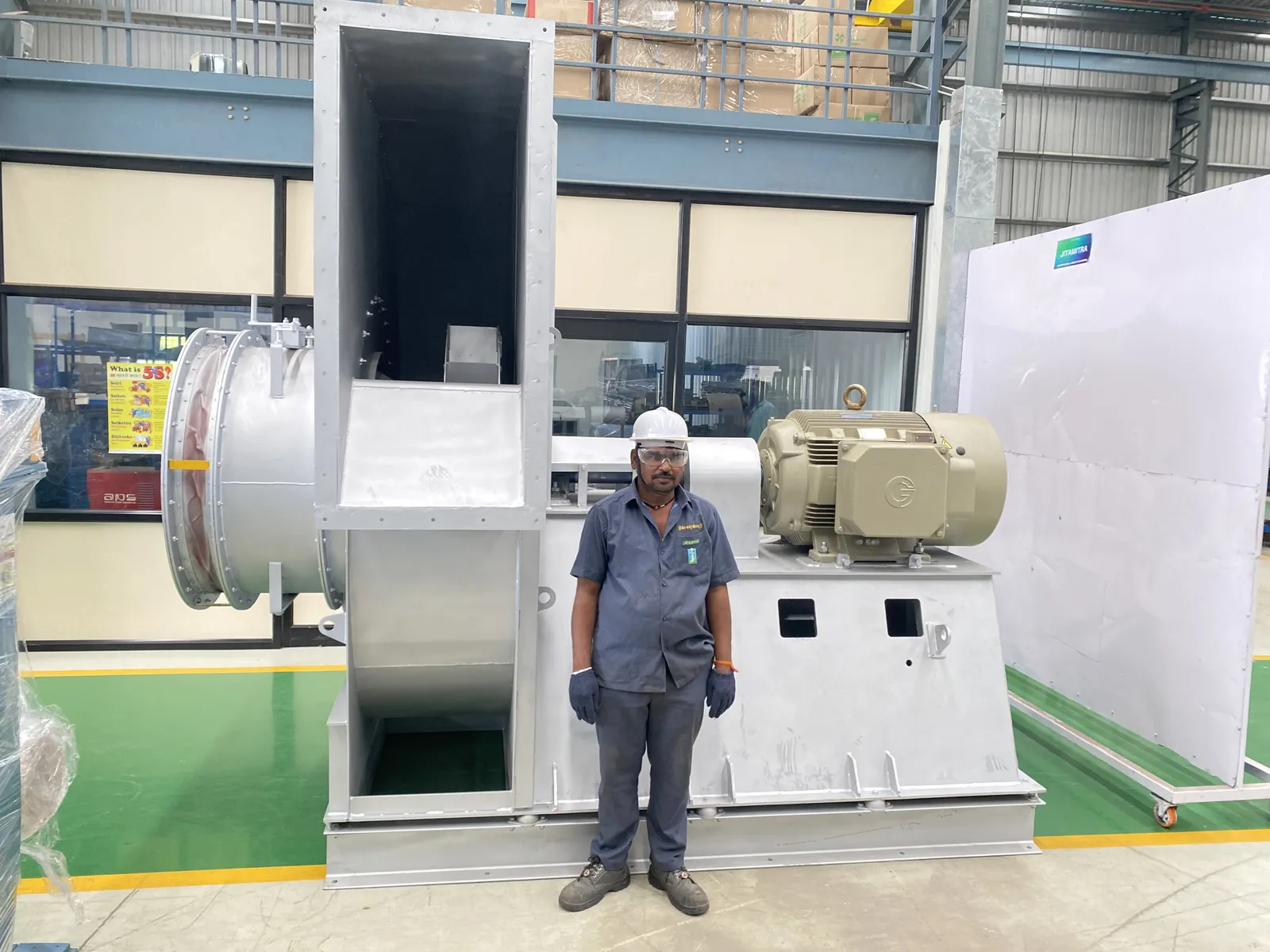
An expansion joint almost never fails on its own - it reports a fault somewhere else. A torn bellows usually means the duct movement exceeded what the joint was specified for, or it was fitted pre-stretched or pre-compressed. A melted or hardened one means the fabric or elastomer was specified below the real gas temperature. Fix the movement or the temperature rating; a like-for-like replacement will fail the same way.
The flexible connector — expansion bellow, canvas or fabric joint, metallic bellow — is the soft coupling between the fan flange and the site ductwork. It has three jobs: keep the fan's vibration out of the duct, absorb thermal growth, take up small installation misalignments. It is not a structural member, it is not an alignment tool, and it is a consumable. Almost everything that goes wrong with it follows from ignoring one of those points.
A torn, split or melted element. A split seam, a fabric tear at the flange, a charred patch. Melting is almost always on the inlet connector of an induced-draught or process fan — the inlet sees the hot gas, the outlet is cooler. If the outlet joint is intact and the inlet is destroyed, that is a temperature/material story, not a mechanical one.
Leakage. Air leaking at the joint, or — on a dust-laden duty — abrasive media eroding the inlet connector until it leaks inward, admitting unfiltered dust straight to the impeller. Watch also for oil weeping at the adjacent plummer block: when the joint takes load it was never meant to, the neighbouring bearing housing is often what actually fails.
Vibration or noise where the joint has stopped decoupling. Restrain the joint — shipping links still fitted, or the element pulled taut — and the duct is hard-coupled to the fan, so the whole train talks. Measure it properly:
State the mounting when you quote a number — the same fan passes on one scale and fails on the other. A rigidly-mounted fan with transit links still across the joint will breach its rigid-mount acceptance limit with no fault present at all.
For noise, judge against the approved GA figure for that fan, not a generic 85 dB. On one 6,500 CMH / 350 mmWC exhaust fan, a "high noise" complaint measured 89 dB against a GA-stated limit of 92 dB — inside spec, and the actual finding was that the transit links had never been removed.
Motor current is not a reliable indicator here. Record it; don't diagnose on it.
Ranked by how often it is actually true in the field:
A fan leaves works run-tested, so the higher prior sits with what happened after dispatch: transport, installation, commissioning, operation, wear. That is where the exposure lies — not a way of ducking the question. Two things still deserve inspection on the supply side: the element's specification (was the inlet material and temperature rating matched to the inlet duty?) and the bought-out element itself — bellows are usually procured items, and an off-drawing or poorly finished connector is a real finding at incoming inspection. Check it early rather than as a last resort.
Isolate first. Fan off, locked out, impeller at rest, duct depressurised. Nothing below is done on a running machine.
Decision points: tear + no support → installation load. Melt → temperature/material. Links still fitted → commissioning. Erosion + dust → operation/wear. Single-axis vibration with hub play → not this failure mode.
Transport & handling - Transit restraints left in. Joint held rigid, duct hard-coupled to fan, vibration and noise straight through. Confirm: the links are still there. - Missing base-frame stiffener in transit. The frame racks on the road and overloads the AVMs and the joint. Confirm: dispatch-specified bracing absent, or AVM pads crushed.
Installation - Joint carrying structural load. Sustained weight tears the element and drags on the adjacent bearing housing. Confirm: against the GA support drawing. - Installation offset absorbed by the joint. Over-extension or compression fatigues the fabric and its seams. Confirm: flange-to-flange gap vs rated face-to-face.
Commissioning - First run with restraints still in, or the duct not yet independently supported. Same two mechanisms — commissioning is the last moment where they are cheap to fix.
Operation & process - Gas temperature above the element's rating. Thermal melt or embrittlement, inlet first. On a 10,000 CMH / 150 mmWC / 100 °C ID fan in a dust-collection plant, the inlet connector melted while the outlet — a different material, rated for its duty — stayed intact. That comparison is the diagnosis. - Abrasive erosion. Media thins the fabric, it leaks, and it then admits dust to the impeller. Confirm: erosion pattern plus dust ingress inside the casing.
Maintenance & wear - End-of-life element. Heat, UV and flex cycles harden the elastomer until it cracks. Confirm: service age, hardness, crazing.
Design and specification. Specify the connector's material and temperature rating against the measured or quoted gas temperature per location — never assume inlet equals outlet. Flag high-temperature and abrasive duties for upgraded fabric at the enquiry stage, not after the first melt.
Commissioning discipline. Two lines on the checklist, each signed off: transit restraints removed and fan and duct independently supported. Take the vibration reading at first run and record it against the correct ISO 14694 category and mounting — that number is your baseline for the next ten years. (Rotating-assembly balance grade is to ISO 21940, G6.3 typical for this class; performance, where verified, is tested to IS 4894 / ISO 5801 / AMCA 210 method.)
Handover. One page to the maintenance team: keep the joint free of load, never use it to correct duct misalignment, inspect for tears and erosion at every shutdown, treat the element as a scheduled-replacement consumable.
Maintenance interval. Fold joint and AVM inspection into the periodic round. Replace on condition — or at a fixed interval on dust-laden and high-temperature duties, where "on condition" tends to mean "after it has already leaked".
If the vibration doesn't settle once the joint is genuinely free — links out, supports in, element sound — the bellow was never the fault, and you need someone to read the machine rather than the symptom. Jitamitra services fans of any make: on-site balancing, vibration diagnosis, bearing and coupling replacement, connector re-specification, and re-rating an existing fan to a changed duty. Send the GA, the duty and the three-axis readings and we'll give you a view before anyone travels.
sales@jitamitrablowers.com · Jitamitra Help Desk +91 8329172325
— Jitamitra Electro Engineering · Technical Services
Engineered for Every Application.
Flow, static, gas temperature, application — or attach a spec, GA drawing or a multi-fan schedule. Engineer to engineer.
ISO 9001:2015 quality system · performance-tested to IS 4894 / ISO 5801 / AMCA 210 method · witnessed FAT on request.
*For our standard range. ATEX and special projects need 5 to 7 working days.
This site sets no cookies of its own. Google Analytics loads only if you accept. It sets two cookies, so we can see which fan topics people actually read. Decline and no analytics loads — the site works exactly the same. What we collect →