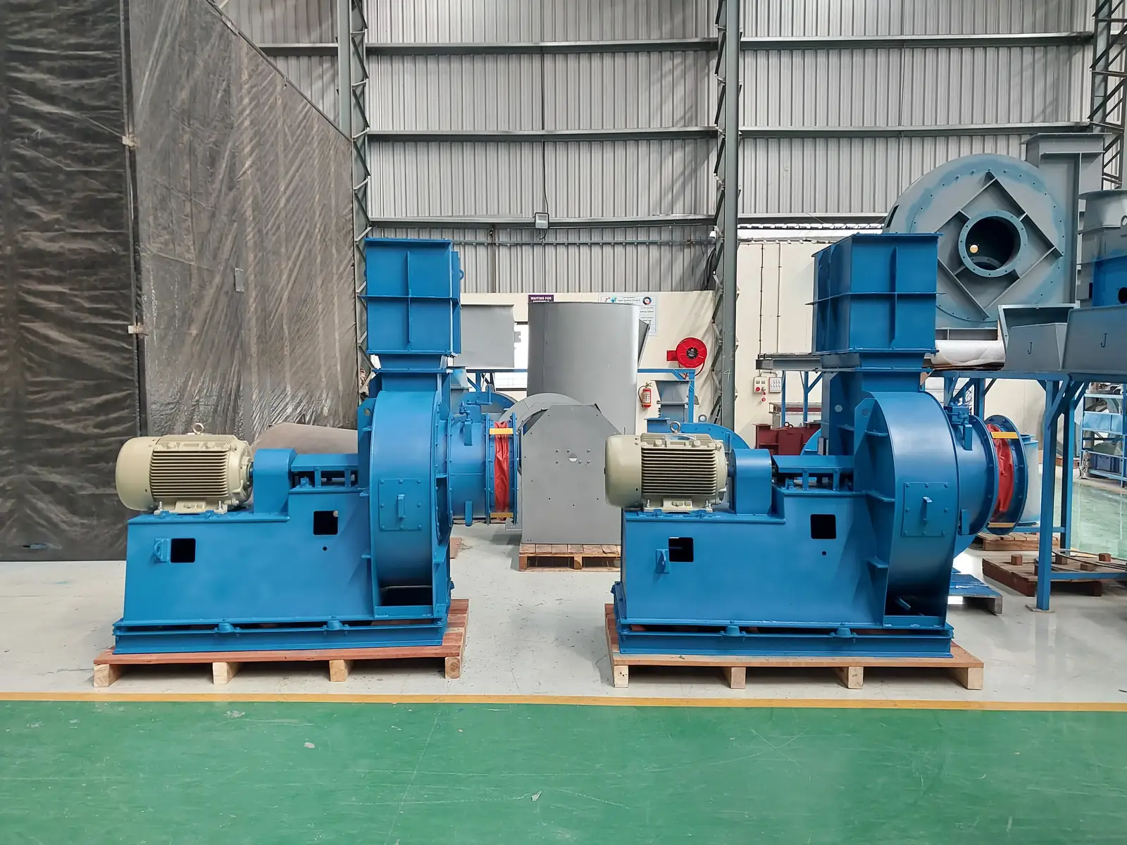
A cracked heat slinger is thermal fatigue - the component is doing its job of dumping shaft-conducted heat and is cycling through a large temperature swing every start and stop. The usual aggravating factors are a slinger starved of cooling air by a lagging or guard that was added later, a fan cycled far more often than it was designed for, and a gas temperature above the one the fan was specified against. Restore the airflow around it before you replace it.
On a hot-gas fan, two components carry the thermal load: the heat slinger (also called the cooling ring, cooling disc, heat-resisting wheel or Plummer-block cooling fan) and the coating system on the casing. The slinger is the finned aluminium disc on the shaft between the impeller back-plate and the drive-end bearing. It spins with the shaft, throws ambient air along the shaft, and keeps conducted process heat off the bearing. It costs very little, and it is the reason the bearing survives.
When it cracks — or when the wrong paint goes onto a hot casing — the failure does not announce itself as a slinger failure. It shows up as noise, vibration or a hot bearing, and it is very often blamed on the motor.
Visual — the primary tell. A radial or circumferential crack in the aluminium slinger web, most commonly at the boss / hub near the Plummer block, where the section change concentrates stress. In advanced cases the disc has broken into pieces. On the coating side: discolouration, blistering, chalking or outright burn-off of paint on the casing or on the gas-volume-control (inlet vane) assembly of a hot-gas fan.
Sound and vibration. A cracked slinger unbalances the rotating assembly. You get rising 1× running-speed vibration and often a periodic knock or rub — once per revolution. Reach for the numbers rather than the ear:
State the mounting before you quote a limit — the two sets are not interchangeable. In practice the absolute number matters less than the trend from the commissioning baseline: a fan handed over at 2.8 mm/s that now reads 5.5 mm/s is telling you something, even though it is still under alarm.
Bearing temperature. A degraded slinger removes shaft cooling, so DE and NDE bearing temperatures climb. Watch for bearing-cap temperature well above the commissioning record — roughly ambient + 40 °C is where you should already be investigating. Every ~15 °C above rated bearing temperature roughly halves grease life, so a "small crack" becomes a bearing failure on a predictable schedule.
Motor current. Usually unremarkable. Not a useful primary indicator here.
Ranked by what we see in the field on hot-gas fans:
A fan leaves works run-tested and balanced, so the higher engineering prior for a slinger failure in service is a lifecycle event — transport, installation, commissioning, operation, wear, or a bought-out component — rather than the build. That is a statement about probability, not a verdict: a crack originating in a casting flaw with no fitment or thermal evidence is a works escape, and should be classified as one. Diagnose first, attribute second.
Isolate first. Lock out and tag out. The fan may have been running hot; let it cool. Open the guard only once the rotor has stopped.
Transport and handling. The finned web is thin cast aluminium and takes a shock load badly. An impact in transit or during unloading cracks a fin or the web. Confirm: crack aligns with an impact witness mark; no thermal discolouration; failure present at first start.
Installation. Over-tightening or forced fitment. Clamping stress plus the stress riser at the boss produces a crack radiating from the fastener. Confirm: crack origin at the grub screw or clamp face, local scoring, clean fracture. Also in this bucket: a mis-seated slinger, which runs out and fatigues.
Commissioning. The wrong coating applied at build or at a site repaint — a cosmetic enamel on a hot-gas casing or inlet-vane assembly, which then chalks, blisters and burns off. Confirm: paint system spec against the datasheet gas temperature.
Operation and process. Thermal fatigue from repeated hot/cold cycling — differential expansion cycle after cycle until a fatigue crack opens at the section change. Dryer and oven exhaust duties with frequent start–stop are the natural home of this failure. Also: gas temperature run above design, which over-temperatures both slinger and coating. Confirm: beach-mark morphology, thermal tint, service age, and the operating temperature log against the datasheet.
Maintenance and wear. Fouled or corroded fins lose cooling effectiveness; shaft heat reaches the bearing, the bearing overheats, and the resulting bearing/Plummer-block/shaft failure takes the slinger with it. Or simply: a missed inspection lets an early hairline grow into a full fracture. Confirm: fin condition, grease condition, bearing temperature history.
Design. Confirm slinger material and section against the actual duty, not the nominal one. Specify a heat-resistant aluminium coating on every hot-gas casing and on inlet-vane assemblies exposed to the gas. Ask for a generous fillet at the slinger boss — the stress riser is where the crack starts.
Commissioning discipline. Torque-controlled fitment. Record a baseline vibration reading and baseline bearing temperature at handover, and note the mounting class (rigid or flexible) alongside them — without a baseline, every later reading is an argument instead of a measurement. Log the commissioning gas temperature against design.
Maintenance interval. Inspect the slinger for hairline cracks at every bearing greasing or inspection interval — two minutes with a torch. Check the fins for fouling and clean them. Keep gas temperature inside the datasheet envelope, and treat any new noise or step change in vibration as an inspection trigger, not a nuisance.
Handover. Make sure the O&M documentation states the temperature and inspection limits, so the operating envelope is owned rather than guessed at.
If vibration is trending up and you cannot resolve the source, if a slinger has cracked twice on the same machine, or if you need the fan back in service with the root cause still open — that is the point to bring in a fan specialist. Jitamitra services centrifugal fans of any make, not only our own: on-site balancing, vibration diagnosis, bearing and coupling replacement, slinger and coating replacement, and re-rating where the duty has moved away from the original design.
Contact: sales@jitamitrablowers.com · Jitamitra Help Desk +91 8329172325.
Jitamitra Electro Engineering manufactures industrial centrifugal fans and blowers, balanced to ISO 21940 (G6.3 typical) and performance-tested to IS 4894 / ISO 5801 / AMCA 210 method. Quality management system certified to ISO 9001:2015. CE and ATEX (Zone 2/22) conformity is self-declared.
— Jitamitra Electro Engineering · Technical Services
Engineered for Every Application.
Flow, static, gas temperature, application — or attach a spec, GA drawing or a multi-fan schedule. Engineer to engineer.
ISO 9001:2015 quality system · performance-tested to IS 4894 / ISO 5801 / AMCA 210 method · witnessed FAT on request.
*For our standard range. ATEX and special projects need 5 to 7 working days.
This site sets no cookies of its own. Google Analytics loads only if you accept. It sets two cookies, so we can see which fan topics people actually read. Decline and no analytics loads — the site works exactly the same. What we collect →