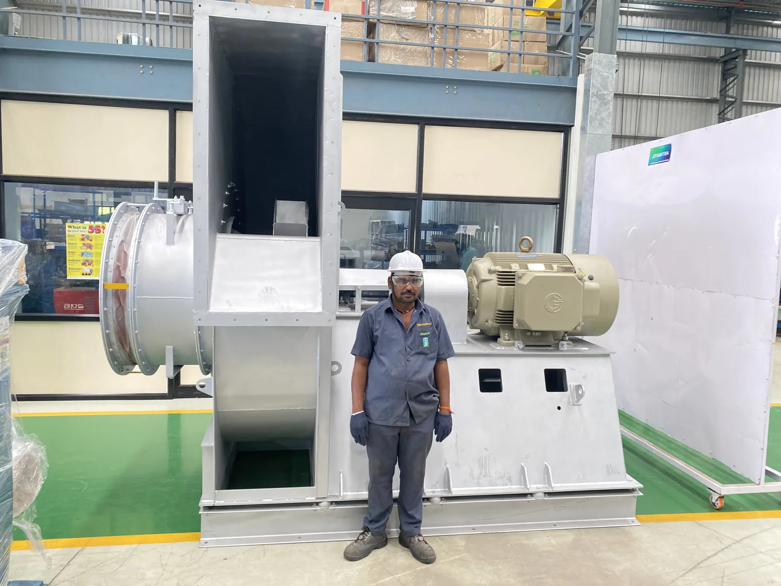
Read the wear pattern before you re-plate. Even erosion across the blade means abrasive loading and too high a tip speed for the duty; wear concentrated at the blade heel or the back plate means the particulate is being thrown to one path; cracking at a weld toe means a stress raiser or resonance, not abrasion. The remedies differ - wear liners in Hardox 400, 450 or 500 and hard-facing for erosion, a design change for cracking.
The impeller is the only part of a fan that is simultaneously highly stressed, fully exposed to the process gas, and spinning. In dirty, wet, hot or corrosive duty it is where the fan dies. This guide covers what impeller damage looks like in the field, how to diagnose it properly, and how to stop it recurring.
Impeller damage rarely announces itself politely. The signatures, in the order engineers usually notice them:
Sound. A new rubbing or scraping note, or a periodic knock or rattle that repeats once per revolution — that once-per-rev signature points at a cracked or partly detached blade. A rising, hollow roar with no gain in flow usually means blades that have worn thin and stopped making pressure.
Vibration. This is the primary tell. Predominantly 1× running-speed vibration that climbs over days or weeks is mass imbalance — uneven wear, shed deposit, or a lost fragment. Quote thresholds against ISO 14694, and always state the mounting condition:
| ISO 14694, BV-3 (general industry) | Rigid mounting | Flexible mounting |
|---|---|---|
| Start-up / commissioning acceptance | 4.5 mm/s r.m.s. | 6.3 mm/s r.m.s. |
| Alarm | 7.1 mm/s | 11.8 mm/s |
| Shutdown / trip | 9.0 mm/s | 12.5 mm/s |
ISO 10816 / ISO 20816 is a separate machine-vibration standard with its own A–D evaluation zones. Don't blend its numbers or its language into the ISO 14694 bands — engineers do this constantly and it produces nonsense acceptance criteria.
The single most useful rule: a step change of 2–3 mm/s overnight means something moved or broke. Stop the fan. Absolute level matters less than the jump.
Motor current. Counter-intuitive, and worth knowing. Blades worn thin no longer generate pressure, so the fan can pull less current as it fails — duty collapse looks like efficiency. A rubbing or partially jammed impeller pulls more and trips overload. Both are impeller faults.
Visual. Thinned or feathered blade trailing edges; grooving on the shroud; holes clean through blades; cracks radiating from blade-to-backplate welds or out of the hub bore; a cracked cooling ring; heavy deposit build-up; coating or FRP loss on the inner casing.
Temperature. Not a direct impeller symptom, but a bearing housing running more than 40 °C over ambient after a vibration event is being fed that vibration. Record it — it tells you the damage has started propagating.
Ranked by what actually turns up on site:
An honest word on priors. A fan leaves works run-tested, so on a unit that has been in service, the higher prior sits with the lifecycle causes above — transport, installation, commissioning, operation, wear, or a bought-out component. That is an engineering statement about where the evidence usually leads, not a rule. It does not mean a specification or supply issue is excluded, and a competent investigation keeps that branch open until the evidence closes it — especially on an early-life failure or a unit still in warranty. Do the diagnosis; don't assume the answer.
Decision points. Wear or grooving with running hours behind it → operation/wear branch. Pitting plus coating loss → corrosion/MOC branch. A crack starting at a weld root with a clean, unworn surface → fatigue or handling. A crack around a boss on a light alloy → over-torque. A missing part plus wrecked bearings and belt → find the primary; the bearing damage is a consequence, not the fault.
Transport and handling. Rare, but real: slinging on the blades rather than the hub leaves a localised dent that can start a fatigue crack. Confirm by a crack origin at an impact mark, inconsistent with any running-hours wear pattern.
Installation. Misalignment or a soft/uneven foundation left uncorrected. Confirm by alignment readings and 2× vibration with an axial component. Left running, it fatigues welds, loosens fasteners and has been known to break foundation bolts.
Commissioning. Residual imbalance accepted at start-up because nobody recorded a baseline. Over-torqued fasteners on soft impellers — a high-torque pneumatic driver on an aluminium fan will crack a boss or a cooling ring. Aluminium needs manual, medium torque. Confirm by the cracked boss and the absence of any wear pattern.
Operation and process — the dominant stage. - Erosion / abrasive wear. Particulate thins blades until they shed section. Erosion rate climbs steeply with particle velocity, which is why abrasive-duty fans should be run slower and armoured. Confirm by thinned leading edges and shroud grooving. - Corrosion / MOC mismatch. Scrubber, plating and effluent duty eats blade and weld metal. Confirm by pitting, coating loss, and the fitted material against the real gas. - In-service loosening. A component works loose, breaks off, and the rotor destroys its own bearings, shaft, belt and duct within minutes. Confirm by the missing part plus the pattern of secondary damage. - Off-design running, surge or over-speed, raising blade stress. Confirm by the actual operating point against the curve.
Maintenance and wear. Deferred replacement of a known-wearing impeller; deposit build-up shifting balance; loss of hard-facing or protective coating over time. Confirm by running hours, deposit mapping and service history.
Design and selection. Match the MOC to gas chemistry, temperature and dust loading at the enquiry stage, not after the first failure. On any genuinely abrasive service, specify hard-facing or bolt-on wear plates by default, and consider a lower tip speed. Protective coatings for wet-corrosive duty.
Commissioning discipline. Verify alignment, dynamic balance (ISO 21940 G6.3), foundation-bolt torque and impeller-hub locking at start-up — and record a baseline vibration reading. Without a baseline, you cannot detect the step change that is the single most valuable early warning you have.
Maintenance intervals. Vibration trending against the ISO 14694 bands for your mounting. Scheduled blade-thickness measurement and weld DPT on abrasive or corrosive service. A re-torque check of impeller fasteners. Deposit cleaning before build-up shifts the balance.
Torque control. Issue torque values with the fan. Mandate manual medium torque on aluminium — no high-torque pneumatic drivers.
Hand-over. Make sure the operating team has the O&M schedule, the vibration alarm and trip thresholds for the actual mounting, and one blunt instruction: stop the fan on any step change in vibration or any new noise.
Jitamitra services fans of any make, not only our own — on-site dynamic balancing, vibration diagnosis, bearing and coupling replacement, impeller re-supply in upgraded materials, and re-rating where the duty has drifted from what the fan was bought for. If you have an impeller that is wearing faster than it should, a vibration trend you can't explain, or a fan you'd like assessed before the next shutdown, we're happy to look at it.
Contact: sales@jitamitrablowers.com · Jitamitra Help Desk +91 8329172325.
Jitamitra Electro Engineering Private Limited. Quality management system certified to ISO 9001:2015. Fan performance tested to IS 4894 / ISO 5801 / AMCA 210 method. CE and ATEX (Zone 2/22) self-declared.
— Jitamitra Electro Engineering · Technical Services
Engineered for Every Application.
Flow, static, gas temperature, application — or attach a spec, GA drawing or a multi-fan schedule. Engineer to engineer.
ISO 9001:2015 quality system · performance-tested to IS 4894 / ISO 5801 / AMCA 210 method · witnessed FAT on request.
*For our standard range. ATEX and special projects need 5 to 7 working days.
This site sets no cookies of its own. Google Analytics loads only if you accept. It sets two cookies, so we can see which fan topics people actually read. Decline and no analytics loads — the site works exactly the same. What we collect →