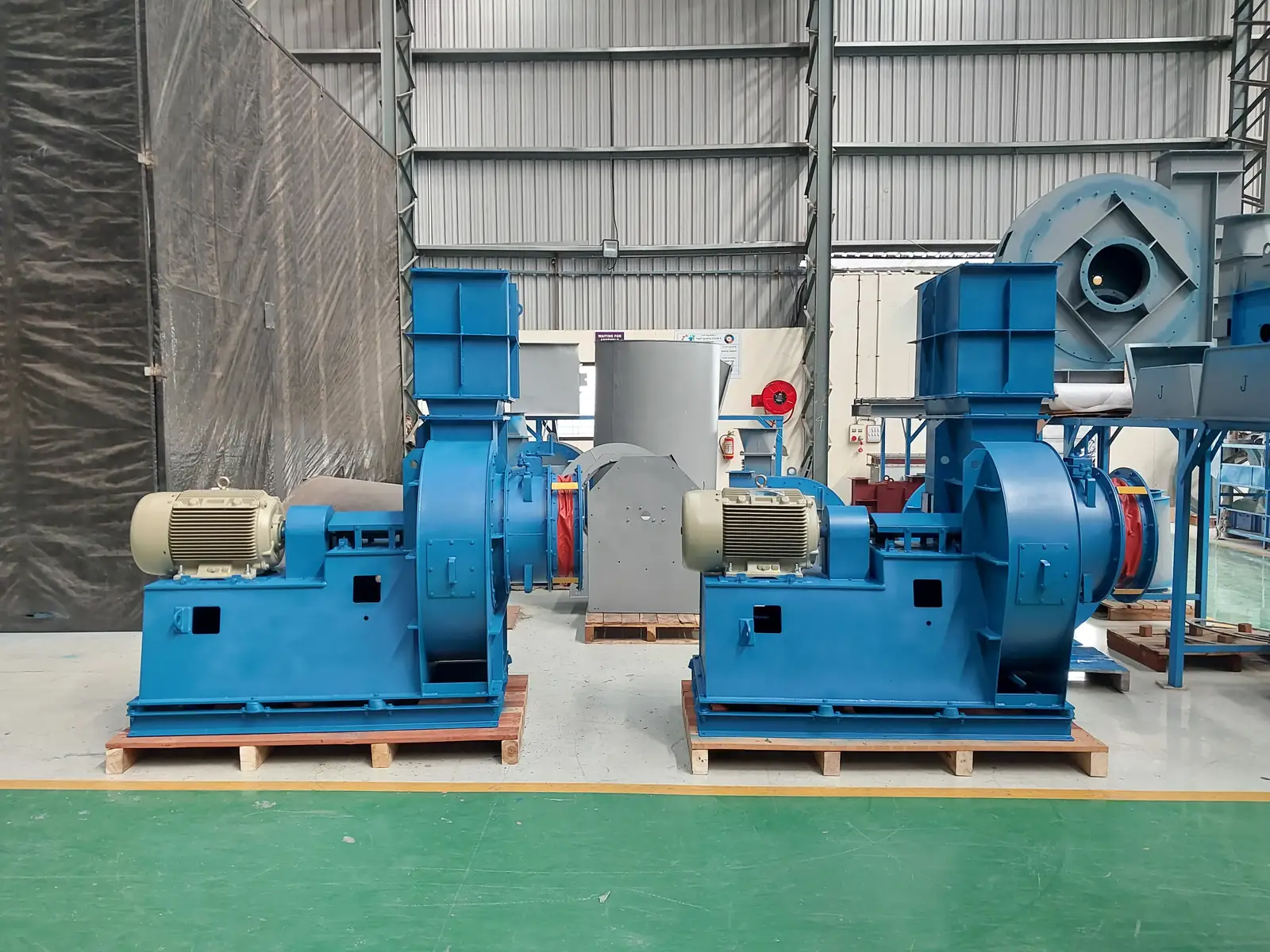
A fan motor that draws over its rated current, or trips its overload every few minutes, is one of the most common calls our service desk takes. It is also one of the most commonly misdiagnosed. The instinct is to suspect the motor or the fan. In the field, the cause is far more often aerodynamic, thermal or mechanical — something about how the fan is being run, not what was built.
This guide sets out how we diagnose it.
What you're seeing
The complaint usually arrives in three words — "motor tripping" or "high current". The useful detail is in what the fan is actually doing when it happens:
- Current above motor nameplate FLC, on one or all three phases, either steady or climbing as the fan warms and loads up. Clamp all three phases; a single high phase is a different problem from three high phases.
- The overload relay or breaker trips — either instantly on start (inrush, or a mechanical bind), or after several minutes of running (thermal, aerodynamic overload). Repeat tripping after a few minutes of clean running is the classic signature.
- Elevated vibration reported alongside the current. Get a number, in three axes, and get it against the right yardstick. Under ISO 14694 the limit depends on the fan's application category and its mounting. For a BV-3 rigidly mounted fan the numbers are 4.5 mm/s r.m.s. commissioning acceptance, 7.1 mm/s alarm, 9.0 mm/s shutdown; flexibly mounted, 6.3 / 11.8 / 12.5. State the mounting when you quote a limit, or the number means nothing. (Keep ISO 14694 separate from the ISO 10816/20816 zone scheme — they are different frameworks and their boundaries are not interchangeable.)
- Belt-drive distress — smoke off the belts, belts cutting up into pieces on a trial run — while voltage and current read perfectly normal and the impeller turns free by hand. That combination is mechanical, not electrical.
- Bearing temperature rise, an unusual hum, or a fan that will not come up to speed.
What it usually means
Ranked by how often we actually find them:
- The fan is running with the damper wide open, or on a system with less resistance than design. It slides out along its curve to higher flow — and shaft power rises with mass flow. The motor is doing exactly what physics says it should.
- The current was measured cold on a hot-gas duty. Power is proportional to gas density. A fan sized for 200 °C, trialled at ambient with the burner off, will overload — and be entirely healthy at temperature.
- Belt-drive fault — slip, misalignment, or a sheave ratio that over-speeds the impeller.
- The overload relay is set below motor FLC. Cheap to check, easy to miss, nuisance-trips a perfectly good fan.
- Electrical supply or motor fault — voltage imbalance, a failing winding, insulation breakdown.
- Fit or balance — impeller hub-to-shaft clearance, key fit, loss of balance — showing up as vibration alongside the current.
A fan leaves our works run-tested against its GA and routine test report, so the higher prior sits with what has happened since: transport, installation, commissioning, operation, wear, or a bought-out component. That is an engineering prior, not a rule. We still pull the test report and GA drawing first on every high-current claim, and check the unit against as-built spec before accepting or dismissing anything.
How to diagnose it
Isolate and lock out before any hand-turning or mechanical check. Work the list in order — it goes cheapest-and-most-likely first.
- Clamp the running current on all three phases and compare against motor nameplate FLC. Note when it trips: on start (inrush or bind) or after minutes (thermal, aerodynamic).
- Check the overload relay dial against nameplate FLC. Set below FLC, it will trip a healthy fan all day.
- Measure supply voltage and phase balance at the terminals, under load. Low or unbalanced supply raises current.
- Establish the damper and system state. Is the fan seeing design system resistance, or is it wide open? Close the damper and watch the current: if the current falls as you throttle, you have an aerodynamic overload, not an electrical fault. That single test settles most cases.
- Density-correct. Take the design gas temperature and the actual gas temperature at the time of the reading, and correct the expected shaft power for density. Do this before condemning a motor. High-negative-pressure and high-temperature duties are the ones that catch people out.
- Confirm rotation and speed. Do this early, not last. A reversed centrifugal impeller still discharges the right way, so it looks like it is working — but on the backward-curved and radial wheels we build it meets the system resistance the wrong way and delivers only 40 to 50% of design flow at higher-than-normal current. High amps alongside poor delivery is exactly that signature, so wrong rotation belongs on this list rather than off it. The arrow on the casing and the direction air actually leaves the outlet are the definitive check. If amps are high and flow is at or above design, look the other way instead: over-flow, low resistance, or density.
- Work the belt drive. Tension by deflection chart; sheave alignment with a straightedge; measure the sheave PCDs and check the ratio against the datasheet. A larger driven-to-driver ratio than specified over-speeds the impeller, and power goes with the cube of speed.
- Check mechanical freedom. Isolated, turn the impeller by hand — feel for rub. Check impeller hub-to-shaft fit, key and taper-lock seating.
- Run a vibration survey in three axes, against ISO 14694 for the correct mounting. Correlate a high reading with the current before you call it electrical. And check the serial number on the reading — a vibration report and a current report from the same plant are not necessarily from the same fan.
- Only now, the electrical work-up: nameplate data, R/Y/B winding resistance, insulation resistance to ground.
The usual root causes
Transport & handling. Impeller knocked out of balance, or the hub bore burred, in transit. Mechanism: imbalance or rub raises torque and current. Confirm: pre-start hand-turn, hub-to-shaft clearance, baseline vibration before first run.
Installation. Ductwork imposing loads or system effect at the inlet; a dislodged or misaligned inlet ring rubbing the impeller. Confirm: inspect the inlet cone/impeller overlap and the inlet duct geometry.
Commissioning. Damper left open, no throttled start. Overload relay set below FLC. Belt over-tension, misalignment or wrong sheave ratio. Cold trial on a hot-duty fan. Confirm: the damper-throttling test, the relay dial, the tension chart, the density correction.
Operation & process. Actual system resistance lower than design, process temperature below design, filters cleaner or ducts different from spec. Confirm: measure real duty — flow, static, temperature — and compare with the GA and test report.
Maintenance & wear. Worn or dry bearings adding drag; glazed, slack or mismatched belts; dust build-up unbalancing the impeller over time; motor bearing failure. Confirm: bearing temperature and vibration, belt condition, current trend over time.
How to fix it
- Open damper / over-run: throttle back to the design operating point and brief the operator on the start sequence.
- OL relay: re-set to nameplate FLC, and record the setting on the commissioning sheet.
- Belt fault: replace cut or glazed belts as a matched set, re-tension to the deflection chart, align the sheaves, and verify the PCD ratio against the datasheet.
- Cold trial on hot duty: demonstrate the density-corrected current. If the trial must run cold, throttle the damper to hold the motor within FLC until the process reaches temperature.
- Electrical: correct the supply imbalance. If winding resistance or IR fails, route the motor to the motor vendor for rewind or replacement.
- Fit / imbalance: correct the hub-to-shaft interference, dynamically re-balance the impeller to ISO 21940 (G6.3 is typical for this class), and re-check vibration to ISO 14694 for the actual mounting.
How to stop it coming back
- Commission to a written checklist. Dampers throttled and opened in steps; rotation confirmed; OL relay set to FLC and logged.
- Density-correct the datasheet. On hot-gas and high-vacuum duties, state the expected current both cold and at operating temperature, so a cold trial isn't misread as a fault.
- Issue a belt tension and alignment card with every belt-drive fan, with a stated re-tension interval.
- Hand over a commissioning baseline — design flow, static, temperature, and the running current at operating temperature. Without a baseline, "high current" is an opinion.
- Keep the routine test report and GA on file. Every fan should be triage-able against its as-built data before anyone books a site visit.
When to call a specialist
Jitamitra services centrifugal fans and blowers of any make — not only our own. If you have worked the damper, the density, the belt and the supply and the current is still where it shouldn't be, that is the point at which on-site vibration diagnosis, dynamic balancing, bearing and coupling replacement, or a re-rating of the fan against its actual duty will tell you more than another set of readings. We can attend site, or work from your test report, GA and readings if that gets you an answer faster.
Contact: sales@jitamitrablowers.com · Jitamitra Help Desk +91 8329172325
Jitamitra Electro Engineering — ISO 9001:2015 certified. Fan performance tested to IS 4894 / ISO 5801 / AMCA 210 method. CE and ATEX (Zone 2/22) self-declared.
— Jitamitra Electro Engineering · Technical Services
Engineered for Every Application.