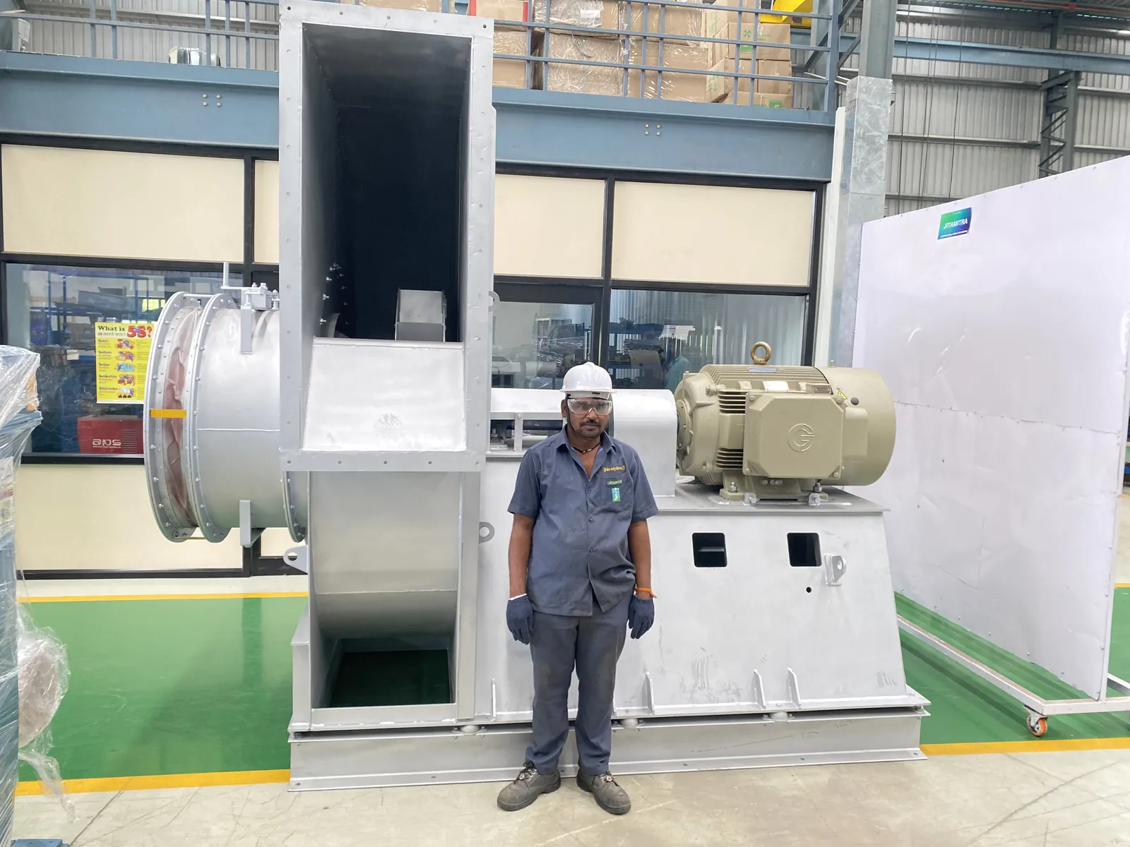
Match the character of the noise to the mechanism. A pure tone at blade-pass frequency is aerodynamic - cut-off clearance or an obstruction in the flow. A rumble at running speed is unbalance. A once-per-revolution knock is looseness or a rub. A rising and falling growl is a bearing. Broadband roar in the duct is velocity and system effect, not the fan. Identify the frequency first, then act on it.
"The fan has become noisy" is a symptom, not a diagnosis. The same three words sit on top of three physically different faults: an aerodynamic one (air recirculating at the inlet, or the wrong system resistance), a mechanical one (coupling rubber, bearings, looseness, rub), and an electrical one (a motor tripping or failing to run, reported as noise). The commonest misdiagnosis in the field is to treat every noise complaint as a bearing job. A large share of them are aerodynamic, and no quantity of new bearings will fix those. This is the procedure we use ourselves — on our own fans and on other makes.
Sound. A broadband rushing or roaring note that rises and falls as you move the damper is aerodynamic. A periodic tonal whine or rumble locked to shaft speed or blade-pass frequency is mechanical. A metallic rasp, or a light tick synchronous with shaft speed, is a rub — impeller kissing the inlet cone, or a coupling guard touching the rubber element.
Vibration. Measure it; don't judge it by hand. Baseline against ISO 14694, and state the mounting condition, because the limits differ:
| BV-3 industrial fan | Commissioning acceptance | Alarm | Shutdown |
|---|---|---|---|
| Rigidly mounted | 4.5 mm/s r.m.s. | 7.1 mm/s | 9.0 mm/s |
| Flexibly mounted | 6.3 mm/s r.m.s. | 11.8 mm/s | 12.5 mm/s |
Do not treat 4.5 mm/s as an alarm, and do not let a rigidly mounted fan drift up toward 11 mm/s because you half-remember a higher number. (The zone boundaries you may be thinking of belong to ISO 10816/20816 — a different standard, a different purpose. Keep them separate.) Spectrally: 1× running speed dominant points to unbalance or coupling; 2× to misalignment; energy at bearing-defect frequencies to bearing damage.
Motor current. Draw above nameplate FLA with a roar means the fan is moving more air than its duty — system resistance is lower than designed. Overload trip is the same fault presenting as "the motor keeps tripping".
Visual. Measure the impeller-shroud-to-inlet-cone overlap: design band 6–8 mm, concentric all round. We have measured 20–22 mm in the field, wide enough to slip a thumb into. Check the coupling rubber for cracking and dust, and the guard-to-rubber clearance.
Temperature. Bearing housing rise above 40 °C over ambient, or an absolute above 70–75 °C, points at bearing or lubrication failure. On hot-gas duties that is a stop item, not a watch item.
Ranked by how often it turns out to be true:
A fan leaves works run-tested and vibration-checked, so the higher prior in the field is on what has happened to it since — transport, installation, commissioning, operation, wear, or a bought-out component. That isn't deflection; it's where the evidence points, and it tells you where to look first.
0. Isolate. LOTO before any hand goes near a rotating assembly. Any step below that runs the fan is done with guards on and people clear of the discharge.
1. Confirm the duty and the complaint. Get the GAD, the fan and motor nameplates, photos or video of inlet, outlet and inside the casing, and measured motor current and voltage. A good share of noise cases resolve here.
2. Listen running, then trip it and listen through coast-down. Noise that stops the instant power is cut is electrical/electromagnetic. Noise that decays smoothly as the impeller slows is aerodynamic — it tracks speed, so on a large impeller it rides the coast-down for tens of seconds. Noise that persists through coast-down but is tonal or impulsive, rather than following the smooth speed decay, is mechanical. Since aerodynamic and mechanical noise both survive into coast-down, the instant-off test cannot isolate aerodynamic noise.
3. Damper sweep — the primary aerodynamic discriminator. Throttle the inlet or outlet damper across its range while watching noise and motor current. If both track the damper, you are in an aerodynamic/system-effect regime, not looking at a broken part.
4. Vibration reading. Horizontal, vertical and axial velocity at both bearings, judged against the ISO 14694 table above for the mounting you actually have. Take a spectrum if you have an analyser and classify by 1× / 2× / bearing frequencies.
5. Static inspection (LOTO). Measure the impeller-cone overlap all round with a feeler gauge or scale — 6–8 mm, concentric. Look at how the cone is made and seated: single spun cone versus fabricated segments, and which way up it sits. Check the pedestal welds. Rotate the impeller by hand: feel for rub, check tip clearance, look for transit dents.
6. Coupling check. Inspect the pin-bush or spider for wear; check the guard for interference. Take an alignment reading, rim-face or laser. Treat parallel (rim) offset above roughly 0.05 mm as suspect. Angular misalignment is a gap difference per unit length — express it as mm per 100 mm of coupling diameter (or in mrad), never as an absolute millimetre figure, and tighten the limit as speed rises.
7. Bearing check. Grease condition and quantity, end float, plummer-block bolt torque, housing temperature under load.
Transport & handling. Impeller or shaft knocked out of true, or the cone dented, in transit: bent geometry gives unbalance or rub — 1× vibration plus a rasp. Confirm by dial-gauge runout and a look for dents. Fasteners loosened by road vibration: confirm by re-torque check.
Installation. Cone seated off-centre or overlap out of the 6–8 mm band, giving recirculation and lost pressure — we have seen a large induced-draught fan on a dust-collection plant delivering barely half its design static for exactly this reason. Coupling misalignment, or a guard fouling the rubber element. Foundation not rigid, giving resonance.
Commissioning. The fan run against the wrong system resistance — open duct, filter bank not yet fitted, damper wide — so it overspeeds airflow, pulls current above FLA, roars and trips. Confirm by damper sweep plus current reading. Also bearings destroyed inside the first shift because the fan was started and run "a different way" during commissioning; we have seen that on a 500 °C hot-gas duty in food and pharma process plant.
Operation & process. Coupling and bearing wear typically surfacing after a restart: on a 30 HP exhaust blower in a steel plant, abnormal noise on restart traced to damaged coupling bolts and rubber, both bearings affected. Dust building up on the impeller creates mass eccentricity and 1× vibration — confirm by cleaning it off and re-reading.
Maintenance & wear. Bearing failure from under- or over-greasing, or from ingress — disproportionately on hot duties, where the grease works near its limit. Confirm by grease condition and housing temperature.
If the noise persists after the damper sweep and the overlap check, or the vibration will not come back inside the acceptance limit, put an instrument and an experienced pair of ears on the machine before you buy parts. Jitamitra services fans of any make — on-site dynamic balancing, vibration diagnosis, bearing and coupling replacement, inlet-cone correction, and re-rating where the duty has moved away from the fan. We are ISO 9001:2015 certified; our CE and ATEX compliance for Zone 2/22 equipment is self-declared. For a second opinion, send the nameplate, the GAD and a short video with the current reading to sales@jitamitrablowers.com, or call the Jitamitra Help Desk on +91 8329172325.
— Jitamitra Electro Engineering · Technical Services
Engineered for Every Application.
Flow, static, gas temperature, application — or attach a spec, GA drawing or a multi-fan schedule. Engineer to engineer.
ISO 9001:2015 quality system · performance-tested to IS 4894 / ISO 5801 / AMCA 210 method · witnessed FAT on request.
*For our standard range. ATEX and special projects need 5 to 7 working days.
This site sets no cookies of its own. Google Analytics loads only if you accept. It sets two cookies, so we can see which fan topics people actually read. Decline and no analytics loads — the site works exactly the same. What we collect →