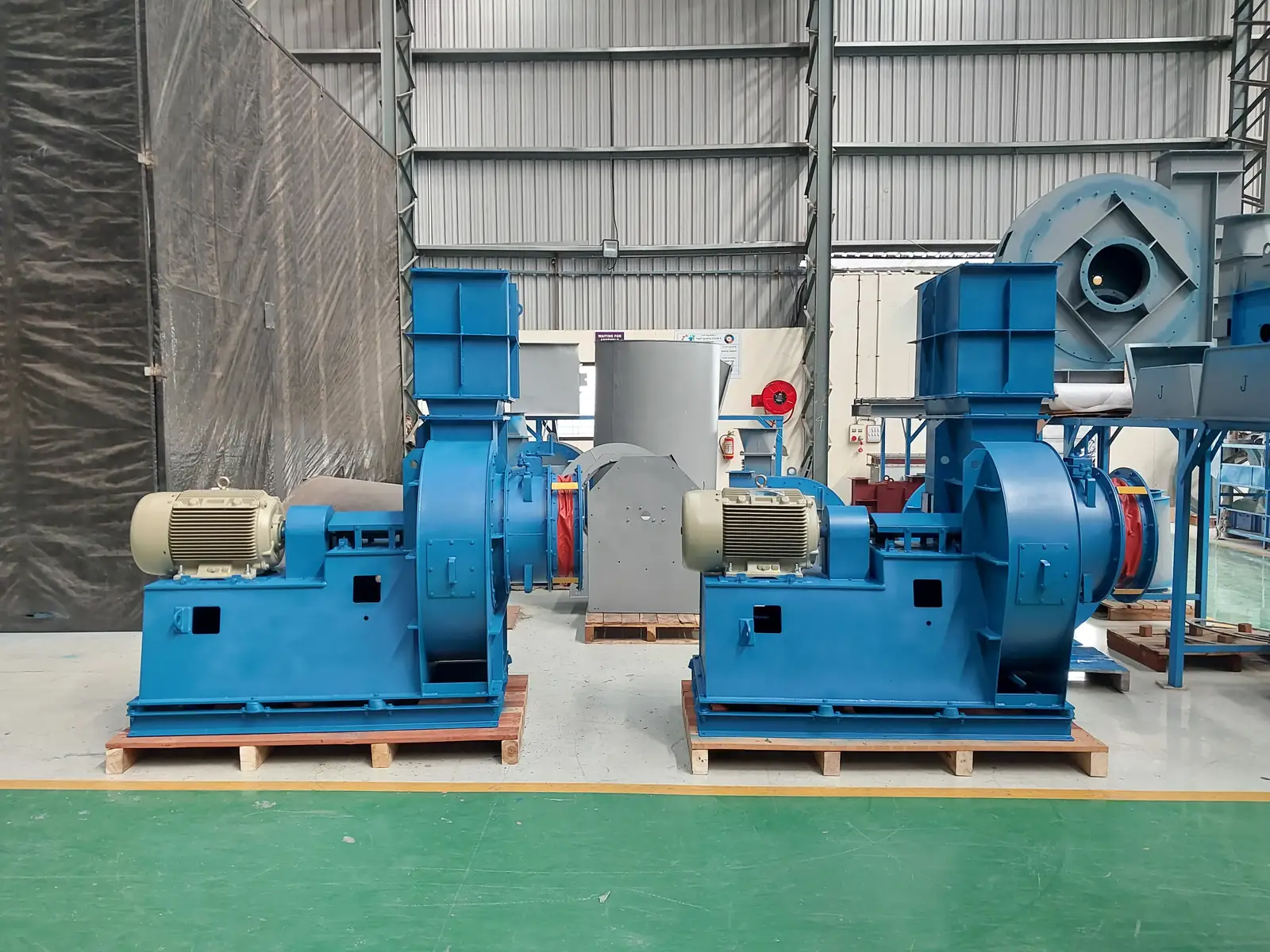
If the wheel was balanced at the works and the fan vibrates on site, the cause is usually structural rather than residual unbalance. Look for a base or pedestal whose natural frequency sits close to running speed, soft foot, grout that never took, duct weight carried on the fan flanges, or a resonance that only appears at operating temperature. A coast-down separates them: resonance falls away at one speed, unbalance tracks speed squared.
A fan that ran smoothly on the test bed and shakes on your foundation is not a mystery. It is a machine whose support, alignment, fit or duty has changed since it was last measured. This is the field procedure our service engineers use to find out which — on any make of centrifugal fan or blower.
The thresholds to reach for — and state the mounting. ISO 14694 for a BV-3 industrial fan:
| Mounting | Commissioning acceptance | Alarm | Shutdown |
|---|---|---|---|
| Rigid | 4.5 mm/s r.m.s. | 7.1 mm/s | 9.0 mm/s |
| Flexible | 6.3 mm/s r.m.s. | 11.8 mm/s | 12.5 mm/s |
A number without a mounting condition is meaningless. On a rigid mount, 7.1 mm/s is already alarm and 9.0 mm/s is stop-territory — do not let a rigidly mounted fan drift up toward 11 mm/s because "the limit is eleven-something". Those figures (6.4 / 11.2 mm/s) belong to the ISO 10816 / 20816 zone boundaries — a different standard with different assumptions. Keep them separate.
A fan balanced (typically to ISO 21940 grade G6.3) and run-tested at works leaves the factory within limits. When vibration appears afterwards, the higher prior is a lifecycle event — the support, the alignment, the fit or the duty changed, not the rotor. Ranked by how often they actually turn up:
That ranking is an opening hypothesis, not a verdict. An out-of-drawing built dimension, or a bought-out component that arrived defective, is a live possibility and should be checked on its merits rather than argued away. Work the mount, alignment, coupling and wear first because that is where the evidence usually is — then follow the evidence wherever it goes.
Safety first. Isolate and lock out the motor. Confirm zero energy at the terminal box, confirm the impeller has coasted to rest, and only then open guards. Nothing below is done on a live machine.
Decision points. 1× radial, roughly equal H and V → unbalance; trim-balance in situ. High 2×, vertical-dominant, soft foot confirmed → re-shim, re-align, re-torque. Worn element or rough bearing → replace. Crack, bent shaft or liberated wheel material → stop the fan and find the driver before you rebuild.
One caution: the vertical-high signature narrows the hypotheses, it does not close the diagnosis. We have seen that exact pattern turn out to be a loose impeller hub, not a soft foot. Confirm the mechanism before you reach for balance weights.
Transport and handling. Foundation and coupling fasteners backed off by road shock → looseness and misalignment; confirm by torque and soft-foot check. Balance disturbed by rough handling or lifting the fan by the wheel; confirm against the works run-test baseline.
Installation. Weak, un-grouted or uneven base — a non-rigid mount amplifies even acceptable residual unbalance and reads vertical-dominant. Coupling misaligned, or its cover set so close it fouls the element. Inlet cone gap wrong: too wide costs performance and can excite flow-induced vibration, too tight rubs. Impeller hub not seated, or an over-clearance fit on the shaft. Hard-ducted, unsupported ductwork pulling on the casing — confirm by loosening the flexible connector and re-reading.
Commissioning. No baseline reading taken, so nobody knows what "normal" was; bolts never torque-marked, so nobody knows what has moved since.
Operation and process. Running off-curve, near stall or over-speed — pulsation plus high current. Progressive unbalance from dust deposits or erosion on the wheel: the norm rather than the exception in dust-collection and scrubber duty.
Maintenance and wear. Aged coupling flexible element — backlash, noise, effective misalignment. Bearing wear or under-lubrication — vibration and temperature rising together. Restart after a long idle period without a re-check, which is when a settled or seized element announces itself.
Eliminate a defective bought-out component (motor, bearing, coupling) early too — an incoming motor with a cracked foot will not be fixed by balancing anything.
Design and detailing. Coupling-cover geometry that cannot foul the element. Correct specified hub-to-shaft fit. Flexible duct connectors at inlet and outlet to break system-effect strain into the casing.
Commissioning discipline — where most of the value is: rigid grouted foundation; soft foot verified with a dial indicator; every bolt torqued and torque-marked; coupling aligned and cover clearance set; cone gap checked against the drawing; and a signed commissioning sheet carrying a baseline vibration reading (V, H, axial, both bearings). A fan without a baseline is a fan you can only argue about later.
Handover. Written mounting and alignment guidance plus the operating envelope, so the fan is not quietly run off-curve for two years.
Maintenance intervals. Periodic coupling-element inspection; bearing condition and lubrication checks; wheel cleaning in dusty and scrubber duty, before progressive unbalance becomes structural damage. Repeat the vibration reading against the baseline — the trend tells you more than any single number.
Traceability. Keep the works run-test report with the serial. When vibration appears three years later, that report is the only honest reference point you have.
Jitamitra services fans of any make, not only our own — on-site trim balancing, vibration diagnosis, soft-foot and alignment correction, bearing and coupling replacement, and re-rating where the duty has moved away from what the fan was built for. If a fan is sitting above its ISO 14694 alarm band and the checks above have not settled the cause, it is worth a call before it becomes a bent shaft.
Contact: sales@jitamitrablowers.com · Jitamitra Help Desk +91 8329172325.
Jitamitra Electro Engineering Private Limited. Quality management system ISO 9001:2015 certified. Fan performance tested to IS 4894 / ISO 5801 / AMCA 210 method. CE and ATEX (Zone 2/22) conformity is self-declared.
— Jitamitra Electro Engineering · Technical Services
Engineered for Every Application.
Most vibration arguments are not about the reading. They are about which reading, taken where, against which limit — settled after the fan is running instead of before.
mm/s RMS, ISO 14694 for a BV-3 industrial fan. Note the mounting column: the same machine on a flexible base is allowed a higher number, so agree the mounting class before anyone measures.
We record the works figure before dispatch and the site figure at commissioning, and hand you both. Where they differ, the gap is the installation — and that is a conversation worth having on the day, not six months later.
Flow, static, gas temperature, application — or attach a spec, GA drawing or a multi-fan schedule. Engineer to engineer.
ISO 9001:2015 quality system · performance-tested to IS 4894 / ISO 5801 / AMCA 210 method · witnessed FAT on request.
*For our standard range. ATEX and special projects need 5 to 7 working days.
This site sets no cookies of its own. Google Analytics loads only if you accept. It sets two cookies, so we can see which fan topics people actually read. Decline and no analytics loads — the site works exactly the same. What we collect →