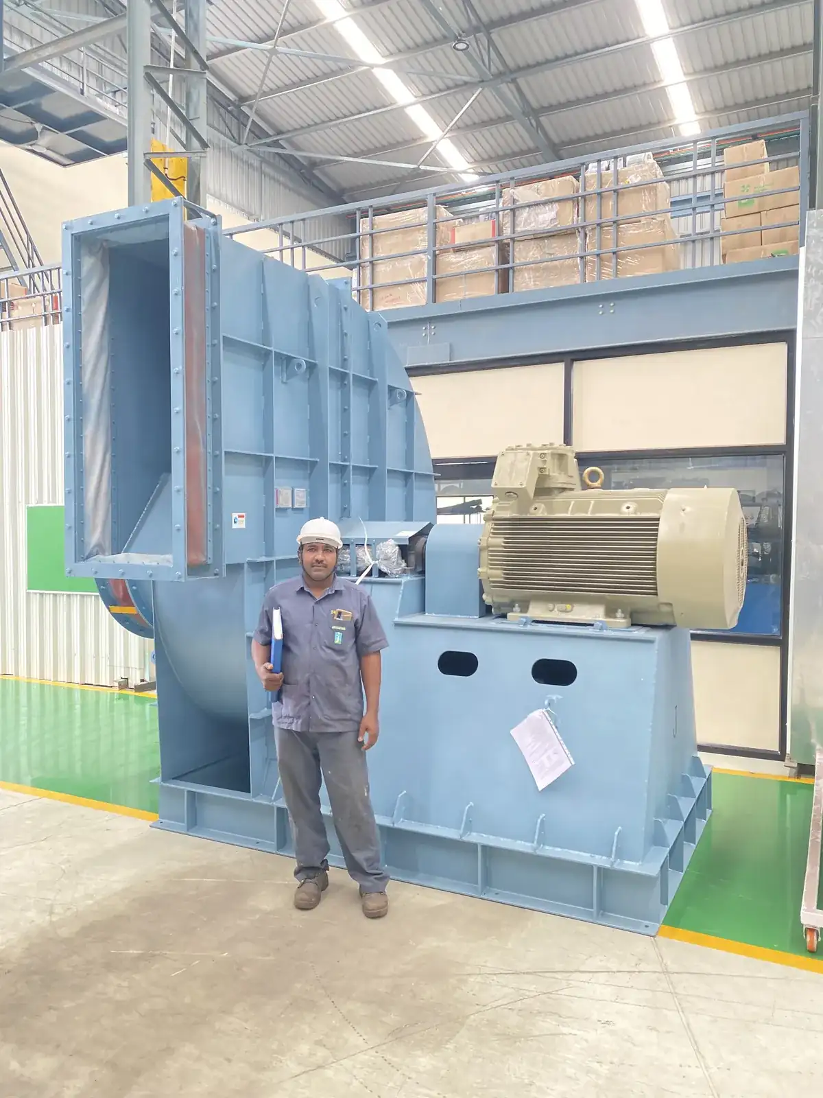
Fan assembly on the Jitamitra shop floor at MIDC Ahilyanagar
Home  /  Resources  /  EC fan control
Resources

EC fan control: one signal wire instead of a drive panel

An EC fan does not have a drive bolted to it. It is the drive. The commutation electronics, the speed loop and the power stage sit inside the motor that carries the impeller, so what leaves your control panel is a signal — not a variable-frequency three-phase feed. That changes your panel schedule, your cable schedule, your commissioning sequence and your redundancy story.

0–10 V / PWMspeed reference
600–2,550r/min over the signal window
<35 ssoft start to full speed
0VFD panels
The drive is the motor

One signal wire instead of a drive panel

An EC fan does not have a drive bolted to it. It is the drive.

The commutation electronics, the speed loop and the power stage sit inside the motor that carries the impeller, so what leaves your control panel is a signal — not a variable-frequency three-phase feed. That changes your panel schedule, your cable schedule, your commissioning sequence, and — if you build the duty out of several fans instead of one — your redundancy story.

This page covers the control side only. Sizes, duties and where these fans belong are on the EC fans page; the selection data we need from you is on selecting an EC fan.

As specified

What the manufacturer actually specifies

Everything below is the manufacturer’s published data for one named model — the Ø450 high-static frame we hold, and the one we can evidence line by line.

We do not assume it is identical across every frame, and we confirm the interface against the specific model before it goes on a quotation.

Control interface — the Ø450 high-static model, manufacturer’s specification
ItemAs specified
Control input0–10 V DC / PWM
Usable signal window1.0 ±0.1 V DC to 9.8 ±0.2 V DC
Speed range over that window600 – 2,550 r/min
Stop thresholdbelow 0.8 V DC in normal running
Auxiliary power output+10 V DC ±0.5, ≤22 mA
Speed feedbackRS-485
Fault feedbackdry contact / RS-485
Soft startunder 35 s to full speed
DutyS1 continuous

Two connections arrive at the fan, on separate terminals: a signal set and the supply. And the fan protects itself — over-temperature shutdown when the internal sensor sees 100 °C, restarting automatically when it falls back to 80 °C; over-current protection; locked-rotor detection; and over- and under-voltage protection.

One honest qualification. The two catalogue lines we are authorised to supply — the high-static Ø310–560 range and the cleanroom Ø133–470 range — do not print a control-input row at all. The table above belongs to the Ø450 model’s own specification, not to the catalogues. Ask us for the interface on the model you are being quoted.

Scope

What disappears from your electrical scope

Gone

The variable-frequency drive: the unit, the enclosure space it needs, the heat it puts into the panel room, and the ventilation for that heat. The screened drive-to-motor cable run, its glanding, and the cable-length limit that comes with it. The separate drive commissioning step — the controller arrives matched to the motor it is fitted to. The belt, the pulleys, the alignment check and the tension schedule.

Not gone

The fan still needs a supply, an isolator, and short-circuit and overload protection designed by whoever does your electricals.

Supply is per model, not per range

The manufacturer’s cleanroom catalogue rates every model in it at 220 VAC, and the high-static catalogue rates every model in it at 380 VAC. For the Ø450 model above, the specification gives 380 VAC rated with an operating range of 380–480 VAC, which puts India’s 415 V nominal inside range. There is no single supply voltage for the range and we will not print one. Tell us what you have at the plenum and we will confirm it against the model before we quote.

The mechanism

Why the control is where the money is

Nothing exotic here — it is the fan laws. Flow falls with speed, pressure with the square of speed, and shaft power with the cube. Run at 80% speed and shaft power falls to roughly half (0.8³ ≈ 0.51). A damper does not do that; it destroys the pressure you paid to generate and the input power barely moves.

An EC fan takes the speed reference directly, so that saving is available without a drive panel in the way, and without an induction motor’s slip and rotor losses to carry at part speed. How much it is worth on your plant depends entirely on your running hours, how much of that time you run throttled, and your tariff — send those three and we will work the arithmetic through on your own numbers. We do not publish a saving or a return figure calculated on someone else’s tariff, because it would tell you nothing.

Integration

What a BMS sees — and what it does not

What it sees

An analogue output channel, one per fan or one reference shared across a bank of them. Write the speed reference, the fan follows it. On the Ø450 model above you can also take speed feedback and a fault indication back — the fault as a dry contact or over RS-485, the speed over RS-485.

What it does not see

RS-485 is a physical layer, not an application protocol. No datasheet, catalogue or specification for any model in our scope names an application protocol. The manufacturer’s AHU application paper mentions such protocols as a general property of EC fans; that is a statement about the technology, not a specification for a model, and we will not list it as an available option on the strength of it.

So raise it early

If your I/O schedule needs a bus connection, a specific register map, or a fault contact on a model other than the one above, raise it in the enquiry. We will get it confirmed in writing against the specific model before it appears on a quotation — and if it cannot be confirmed, we will tell you that instead of guessing. A control schematic drawn around a feature that turns out not to exist gets discovered at commissioning, which is the worst possible place to discover it.

Arrays

An array of small fans against one large AC fan

The manufacturer’s AHU paper documents one retrofit: five Ø450 high-static EC fans replacing one belt-driven centrifugal fan.

26,600 → 39,600
m³/h · before → after
18.8 → 11 kW
input power · before → after
0.707 → 0.278
kW per 1,000 m³/h
~61%
lower specific power

The paper puts the energy saving at “up to 41.5%” — which is just the drop in input power. It is not a like-for-like comparison and we will not present it as one, because the unit moved 49% more air at the same time. The comparison that is like-for-like is specific power, and that is the pair of figures above: the paper’s own two rows, divided.

Redundancy

The manufacturer’s words: “when an individual fan fails, the remaining fans continue operating normally”. A single fan gives you no such thing. Note that this holds with backdraft or isolation dampers on each unit — without them a stopped fan is a recirculation path.

Access and turndown

Several small plug fans go through a standard AHU door; one large replacement fan usually means panels off, or a crane. And you get turndown by count as well as by speed — stage fans off and run the rest nearer their best point.

What an array does not give you

Staging intelligence. No document in our scope specifies master–slave, cascade or built-in sequencing logic. Assume the staging decision sits in your BMS or your panel, and design it there. Bearing life on this range is 40,000 hours L10 minimum, qualified as at nominal supply voltage, full speed, in a 40 °C ambient — we quote it with that qualifier attached and do not extrapolate it.

Honest limits

Where EC control is the wrong answer

Clean air only, and within a rating that belongs to a named model rather than to the range. The Ø450 high-static model we hold reads −25 to +50 °C operating temperature. Other frames in the range are rated differently, and some stop lower at the top of the band — ask us for the rating on the model you are being quoted, and we will give it to you in writing with the model number on it.

Our reading of the manufacturer’s specification is that this range is for clean supply air, make-up air, AHU and downstream-filtration duty. It is not for solvent-laden or overspray paint-booth exhaust, not for classified hazardous areas, not for air hotter than the model’s own rating, and not for abrasive dust. The clean side of your paint shop and the dirty side need different fans, and we make both — for the loaded and hot duties we build a purpose-engineered centrifugal fan in our own works at Ahilyanagar. See the fan families →

Before we can quote

What we need to quote a control scheme

Duty point

Airflow in CMH and static pressure in mmWC or Pa, at the fan.

Where the reference comes from

A local potentiometer, an analogue output from your panel, or a BMS channel.

Feedback needed

Whether you need speed feedback or a fault indication back, and in what form.

Supply and protection

Supply available at the plenum, and the protection philosophy your electricals follow.

One fan or an array

And what has to keep running if one unit stops.

Air temperature

At the fan, and the plant-room ambient around it.

Hours and tariff

Hours per day, days per year, how much is at reduced flow, and your rate.

Who makes them

These fans are built by JUPI AirTech — JUPI Air Technology (Nanjing) Ltd. Jitamitra Electro Engineering Private Limited is their Exclusive Authorized Distributor — EC Backward Curved Centrifugal Fans, India, under authorisation J26D061701IN dated 17 June 2026.

You buy from Jitamitra, not from an import invoice. We are your supplier of record and your single point of accountability — selection, landed cost, supply, installation, commissioning, spares and field service, from Ahilyanagar, by the same engineering and service teams that look after the fans we build ourselves. More on the arrangement →

Performance and rating figures on this page are the manufacturer’s published data for the model named against them, measured by the manufacturer. They have not been independently verified by Jitamitra and are subject to the manufacturer’s tolerances. Nothing on this page constitutes a warranty given on the manufacturer’s behalf. The binding specification is the one on our quotation for your duty.

Related: EC fans — the range and how they work · Retrofitting an AHU to EC · Selecting an EC fan · Cleanroom and pharma AHU · Engineering, energy and advisory · Our own centrifugal fan families

Ready to size one?

Send us the duty point and the control interface you need.

Airflow, static pressure, running hours, tariff, and how the fan is to be commanded. We will come back with a selection and a landed price — normally within three working days.*

Get a quote Talk to engineering

Jitamitra Help Desk +91 83291 72325 · sales@jitamitrablowers.com
*For our standard range.