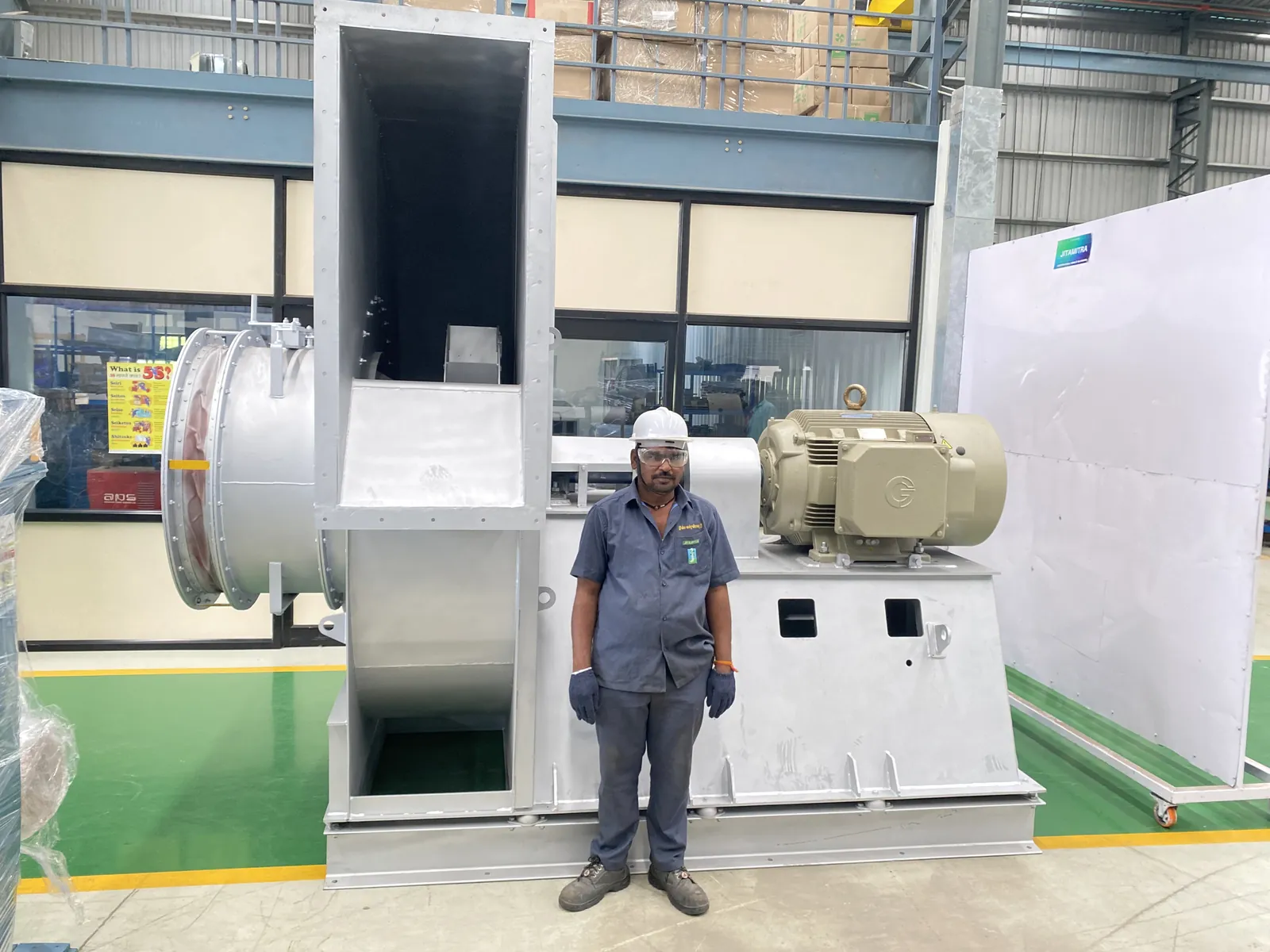
| Who | a heat-treatment furnace installation |
| Equipment | a Jitamitra high-pressure blower for the furnace's purge and cooling air — 8,300 CMH at 900 mmWC, 37.3 kW motor |
| Complaint | flow measured on site at 7,160 CMH; 835 mmWC with all valves open; motor current 53 to 58 A against a 63 A motor rating; a question about enlarging the impeller |
| Service | review of the site readings, the works test record, and the duct layout drawing and photographs, October 2026 |
| Response | a written engineering explanation, and an on-site inlet test offered |
| Result | Works test (IS 4894 procedure, cross-checked with AMCA 210-16): 8,400 CMH at 925 mmWC against 8,300 CMH at 900 mmWC specified. The layout carries sharp bends, T-joints and reductions in duct diameter. The record closes at the explanation and the offer of an on-site inlet test; the customer's confirmation is not on file. |
A heat-treatment furnace leans on a high-pressure blower for its purge and cooling air. This one was specified for 8,300 CMH at 900 mmWC and tested at our works.
Three readings came back from site: 835 mmWC available with all valves open, falling once the cooling circuit was connected; a motor current of 53 to 58 A; and a measured flow of 7,160 CMH. Two conclusions were drawn from them — that the blower was short of flow, and that, because the motor was not drawing its full 63 A rating during purging with every valve open, the blower was not doing its work. The end user asked whether the impeller could be made larger or wider.
We took the questions one at a time.
1. Is the blower on its duty? The works test, run to the IS 4894 procedure and cross-checked with AMCA 210-16, recorded 8,400 CMH at 925 mmWC against the 8,300 CMH at 900 mmWC specified.
2. What does the site gauge tell us? A pressure gauge on the duct is a reference reading. It does not give the fan's exact operating point, and it can read lower than the pressure actually available. The site method that does: at the fan inlet, close the inlet fully and read the shut-off pressure; open it until the gauge reads 900 mmWC; measure the air velocity there; and work out the flow from the open area. We offered to run that test on site.
3. Why does the motor not reach 63 A? The test record puts the duty at 29.5 kW and 51 A at 32 °C, and 54.7 A with the system fully open. The motor is chosen to cover the fully open condition, and the next standard motor that does is 37.3 kW, rated 63 A. A rating is the most a motor can carry, not a figure the fan is meant to draw — with every valve open, this blower is not expected to reach it.
4. Where did the flow go? The duct layout drawing and photographs showed sharp bends, T-joints and reductions in duct diameter. Each adds resistance; together they move the system's operating point to a lower flow than the one specified. A blower holds its curve; the system decides where on that curve it runs.
5. Why not a larger impeller? A larger or wider wheel draws more power. On this machine it would push the current too high. A resistance problem is solved in the ductwork.
Before a blower is condemned for low flow, three things settle most of it: the works test point, a measurement at the fan inlet on site, and the duct layout. And a motor drawing less than its rating is not, on its own, a weak fan — motors are sized to the next standard rating above what the fan needs.
We service centrifugal fans and blowers of any make — root-cause diagnosis, on-site testing and correction, and a written maintenance regime you can run.
— Jitamitra Electro Engineering · Technical Services
Engineered for Every Application.
Not necessarily. Motors are sized to the next standard rating above what the fan needs. Here the duty was 29.5 kW and 51 A, and 54.7 A fully open, on a 37.3 kW motor rated 63 A, so the blower is not expected to reach 63 A.
As a reference only. It does not give the fan's exact operating point and can read lower than the pressure actually available. A measurement at the fan inlet, shut-off pressure first and then the air velocity at the duty pressure, gives the fan's own point.
Not when the ductwork is the cause. A larger or wider wheel draws more power, and on this machine it would have pushed the current too high. Sharp bends, T-joints and duct reductions add resistance, and that is where the flow goes.
The works test, run to the IS 4894 procedure and cross-checked with AMCA 210-16, recorded 8,400 CMH at 925 mmWC against the 8,300 CMH at 900 mmWC specified.
The record closes at our explanation and the offer of an on-site inlet test; the customer's confirmation is not on file.
Flow, static, gas temperature, application — or attach a spec, GA drawing or a multi-fan schedule. Engineer to engineer.
ISO 9001:2015 quality system · performance-tested to IS 4894 / ISO 5801 / AMCA 210 method · witnessed FAT on request.
*For our standard range. ATEX and special projects need 5 to 7 working days.
This site sets no cookies of its own. Google Analytics loads only if you accept. It sets two cookies, so we can see which fan topics people actually read. Decline and no analytics loads — the site works exactly the same. What we collect →
