Plug/plenum centrifugal AHU fan with airfoil impeller on the Jitamitra shop floor
Home  /  Applications  /  AHU supply / return
Applications

AHU supply / return fans — efficient, quiet, built to run 24×7.

AHU supply and return fans are the air-movers inside built-up and packaged air-handling units — pushing conditioned air to the space and drawing it back through the return. The air is clean, so nothing here erodes or corrodes. What decides the fan is the electricity bill and the sound level: it runs almost every hour of the year, so a point of efficiency and a decibel of noise both compound over a long life. We build plug/plenum and housed AHU fans across commercial HVAC, data centers, pharma and food plants — sized onto the best-efficiency point of the wheel, up to 2,00,000 CMH, 2,000 mmWC and 400 HP. Executed on 36 customer duties.

2,00,000CMH max flow
highstatic efficiency
<75 dB(A)on acoustic build
24×7continuous run
15,000+
fans built since 2011
200 HP
VFD test rig · IS 4894 / AMCA 210
99%
on-time delivery
3
working days to quote — always
INSIDE THE AHU · CLEAN CONDITIONED AIR · PLUG / PLENUM OR HOUSED · SUPPLY AND RETURN
What it does

Two air-movers in one unit — supply pushes to the space, return pulls it back.

An AHU supply fan sits after the coils and filters, pushing conditioned air out through the supply duct to the occupied or process space. The return fan draws that air back through the return path, holds the unit and duct system in balance, and hands it to exhaust, mixing or recirculation. Both handle clean air — so the engineering is about efficiency, sound and a stable curve, not wear.

  • 01
    Supply

    Conditioned air to the space through the coil and filter bank. Internal AHU resistance is real — cooling coil, heating coil, filters and attenuators can total 250–900 mmWC before a metre of external duct is added.

  • 02
    Return

    Air drawn back from the space, keeping the unit and building in balance so the room holds its target pressure. Return static is usually lighter than supply — but the two fans must track together across VAV turndown.

  • 03
    Run efficient and quiet

    At 6,000–8,760 h/yr the fan is on almost continuously. There is no wear to design against, so the whole design shifts to static efficiency, sound power and stable part-load control.

INDUCED-DRAFT CENTRIFUGAL FAN Single-width single-inlet — scroll cut away to reveal the impeller inlet expansion joint MOTOR IE3 / VFD GAS IN GAS OUT n 1 2 3 4 5 6 7 8 9 10 1 Inlet cone (bell-mouth) 2 Backward-curved / radial-tipped impeller 3 Spiral volute casing 4 Replaceable AR wear plates (volute throat) 5 Shaft 6 Plummer-block bearings (L10 ≥ 40,000 h) 7 Shaft cooling disc (>400 °C duty) 8 Pedestal / base frame 9 Drive — motor + coupling 10 Outlet flange + duct take-off
Fig. 1Plug/plenum AHU fan — unhoused airfoil impeller on the motor shaft, discharging into the plenum section of the air-handling unit. Numbered components keyed below the drawing.
Why it is hard

Clean air, but three things quietly decide the lifetime cost.

Nothing erodes or corrodes an AHU fan, so it is easy to under-engineer. But it runs nearly every hour of the year, which means efficiency is the whole life-cycle cost, sound carries straight into occupied space, and the two fans have to stay well-behaved across deep VAV turndown. A 75 HP supply fan run several points below its best static efficiency wastes tens of MWh a year at 8,000 h/yr — over a 20-year life the fan choice dwarfs its own purchase price.

01 — EFFICIENCY

Continuous-run operating cost

AHU fans run near-continuously, and fan energy is the largest single electrical load in most air-handling systems. A wheel held even a few points below its achievable efficiency burns money every hour the AHU is on — and it is on almost always.

How we engineer it out

Airfoil-bladed impellers for high static efficiency on the primary supply and return duty, backward-curved / backward-inclined where cost or space rules; every fan sized onto its best-efficiency point, not a catalogue near-fit.

02 — NOISE

Sound into occupied space

The AHU often sits one wall away from offices, wards, labs or a data hall. Blade-pass tone and low-frequency rumble carry down the duct and through the plant-room wall into space where people work — where an NC/RC target is a contract line, not a nicety.

How we engineer it out

Low-tip-speed airfoil wheel selection, sound-power predicted per octave band, and inlet/discharge attenuator scope engineered to the room criterion — <85 dB(A) @ 1 m standard, down to <75 dB(A) with acoustic treatment.

03 — TURNDOWN

Stability across VAV part-load

On a VAV system the AHU spends most of the year well below design flow. A plug/plenum fan sized only at the design point can drift toward stall as boxes close, adding rumble and hunting the supply/return balance the building depends on.

How we engineer it out

Duty point set on the stable, falling side of the wheel curve; VFD as default so speed tracks demand without a throttling loss; supply and return fans matched so the pair turns down together and the space holds pressure.

How we design for it

Every choice is documented on the GA drawing you sign off — before we cut metal.

We don't sell a catalogue near-fit. The fan is engineered to your external and internal static, run hours, sound criterion, turndown range and AHU-section footprint.

  • Impeller & configuration — Plug/plenum (unhoused) airfoil wheel for the compact AHU section and clean discharge into the plenum; housed backward-curved / airfoil where a ducted volute discharge is specified. Static efficiency shared on enquiry, depending on configuration and duty size.
  • Acoustics — Sound power predicted per octave band, low-tip-speed wheel selection, and attenuator scope sized to the room criterion — <85 dB(A) @ 1 m standard, <80 dB(A) with inlet/discharge silencers and acoustic-lagged casing, <75 dB(A) with an acoustic enclosure.
  • Control — VFD as default — AHU flow tracks occupancy and load across a wide range; VFD speed control is more efficient than a discharge damper at part-load because it avoids the throttling loss, and holds space pressure across VAV turndown. VFD is our default; supply and return drives are matched to track together.
  • Materials & hygiene — Mild steel + epoxy coating standard; stainless steel wheel and cleanable, crevice-minimised construction where the AHU serves pharma, food or a wash-down environment; aluminium impeller for ATEX Zone 2 where an AHU handles a classified return air path.
Engineered to your duty point

We size the fan onto its best-efficiency point — then prove it on the rig.

No catalogue fan forced onto your spec. Your operating point is engineered onto the best-efficiency region of the selected wheel — with the duty set on the stable, falling side so the fan behaves across VAV turndown — and verified on the 200 HP VFD test rig before dispatch.

avoid: unstable 0 40,000 80,000 1,20,000 1,60,000 2,00,000 VOLUME FLOW RATE  [ CMH ] 0 500 1000 1500 2000 STATIC PRESSURE  [ mmWC ] 0 25 50 75 100 STATIC EFFICIENCY  [ % ] Fan static pressure System resistance Static efficiency BEP 82% DUTY POINT 1,20,000 CMH · 450 mmWC Fan static pressure System resistance Static efficiency
Fig. 2Representative AHU-fan characteristic — fan static pressure, system resistance and static efficiency vs. flow, with the duty point engineered onto the best-efficiency region and the part-load path staying on the stable side of the curve. Illustrative; every fan is sized to its own duty.
Capability envelope — AHU service

What we can supply, and where it stretches on application.

ParameterStandardOn application
Volume flowup to 2,00,000 CMHhigher on enquiry
Static pressureup to 1,500 mmWC (external + AHU-internal)up to 2,000 mmWC on high-resistance builds
Air temperatureambient conditioned air, −10 to 60 °Chigher on process-air / recirculation service
Static efficiencyhigh static efficiencyhigher on airfoil high-efficiency builds
Sound level<85 dB(A) @ 1 m<75 dB(A) with acoustic enclosure
Drive powerup to 400 HPhigher with custom motor sourcing
Speed600–1,800 RPM typicalper duty + sound limits
Balance qualityISO 21940 G6.3G2.5 / G1.0 on application

The envelope above covers the great majority of AHU supply and return duty. Most AHU fans sit at moderate flow and low-to-moderate static — the static shown is the sum of the external duct system and the AHU-internal resistance (coils, filters, attenuators), which alone can run 250–900 mmWC. The air is clean, so wear protection is not required and the design is led by efficiency and sound. Bearing life is a design target of L10h ≥ 40,000 h continuous — a real consideration here because the fan runs almost every hour of the year — with longer L10 on application. For duty beyond the envelope we engineer to spec and quote on enquiry.

How a Jitamitra AHU fan is specified

Specified, not picked from a shelf.

The same engineering language carries from your enquiry to the GA drawing to the nameplate — expressed in the standard AMCA conventions.

Specification fieldOptions
Arrangement (AMCA 99)Arr. 4 (direct, impeller on the motor shaft — the plug/plenum default) / Arr. 1 (overhung, fan bearings) / Arr. 8 (overhung on common base) / Arr. 9 (overhung, motor side) / Arr. 10 (overhung, motor inside base) — selected by drive, access and AHU section.
ConfigurationPlug / plenum (unhoused, discharging into the AHU plenum — default for built-up and packaged AHUs) / housed SWSI or DWDI where a ducted volute discharge is specified.
Width / inletSWSI (single width, single inlet) default; DWDI (double width, double inlet) for high flow at moderate static in a large built-up AHU.
Wheel typeAirfoil-bladed (default for best efficiency and lowest sound on clean air) / backward-curved or backward-inclined (where cost, space or a wash-down clean-out rules).
Class (by pressure / outlet velocity)Class I / II selected from the duty point on the pressure-vs-outlet-velocity limits; most AHU duty sits in Class I / II, higher class = heavier construction for higher pressure and tip speed.
Materials of constructionMild steel + epoxy coating (standard) / stainless steel wheel and cleanable, crevice-minimised construction for pharma, food and wash-down AHUs / aluminium impeller for ATEX Zone 2 on a classified return path.
DriveDirect-coupled (plug/plenum default) / V-belt / VFD (default for VAV turndown control). Drive up to 400 HP across the envelope; speed typically 600–1,800 RPM, with supply and return drives matched to track together.
Discharge & rotation (AMCA orientation)Plug/plenum discharges into the AHU plenum (no scroll); on housed builds rotation CW or CCW (viewed from drive side) with discharge angle per AMCA — e.g. TH/BH/UB/DB — set to match the duct take-off and AHU footprint.
Accessories & acoustic scopeVFD control (matched supply/return); inlet and discharge silencers, acoustic-lagged casing and inlet cone / bell-mouth for efficiency and low sound; flexible connection / expansion joint at the AHU interface; anti-vibration mounts; drain and inspection doors; acoustic enclosure for <75 dB(A).
The proof, not the promise

We test before we ship — and you're welcome to witness it.

Every job's performance is verified at our works on the 200 HP VFD test rig, to the AMCA 210 / ISO 5801 method, before dispatch.

  • Customer-witnessed FAT on request — at no extra cost
  • Rotors balanced to ISO 21940 G6.3 as standard (G2.5 / G1.0 on application) before they leave the floor
  • Full NDT in-house — DP, MPI, UT, RT — to what the duty demands
30+ INDUSTRIES · 45 APPLICATION / DUTY TYPES
Where our AHU fans run

Proven on the clean-air, run-all-year side of HVAC.

Commercial HVAC & Buildings

Built-up and packaged AHU supply/return for offices, malls, hospitals and airports — efficiency-led, low-noise, VAV-controlled.

Data Centers

CRAH and AHU supply/return for containment cooling — high efficiency, matched N+1 redundancy, VFD tracking IT load.

Pharmaceuticals

AHU supply/return on utility and non-classified HVAC — stainless, cleanable construction (the cleanroom AHU duty is a separate page).

Food & Beverage

Process-area AHU supply/return with wash-down-ready, crevice-minimised build for hygiene.

Semiconductor & Electronics

Fab-support and utility AHU air movement where efficiency and vibration limits are tight.

Institutional & Healthcare

Hospital, lab and campus AHU supply/return where sound criterion and 24×7 uptime govern.

Textile & Light Industry

Humidification-plant and general process AHU supply/return at high run hours.

Your process

45 application/duty types engineered. Tell us yours.

Standards & conformity

Stated precisely — because procurement checks.

What our marks mean, in the words that survive an audit.

Performance

Tested to the AMCA 210 / ISO 5801 method, in-house on our 200 HP VFD rig. Tested-to-method — not AMCA-certified.

Quality system

ISO 9001:2015 — third-party certified. Our only third-party certification.

CE conformity

Self-declared per 2006/42/EC + 2014/35/EU (Module A). A self-declaration, not a notified-body certificate.

ATEX conformity

Self-declared, Zone 2/22, Category 3, per 2014/34/EU, where the area classification calls for it.

Oil & gas duty

Designed and built to API 673 as project-specific scope.

Welding

ASME Sec IX qualified welders + WPS for every joint.

Balance

ISO 21940 — G6.3 minimum, G2.5 / G1.0 on application.

Vibration

ISO 20816 evaluation; ISO 14694 for fan-specific limits.

Lead time & process

From enquiry to a tested fan on your dock.

StageStandard dutyAPI-673 / engineered
Offer / quotation3 working days — always7–10 working days
GA drawing for approval2–3 weeks from PO3–4 weeks from PO
Manufacture + balance + paint6–10 weeks10–14 weeks
Performance test + witnessed FAT~1 week1–2 weeks
Order-to-dispatch (total)9–14 weeks14–20 weeks

Shutdown-driven replacements: we have shipped fans within 6 weeks of a clean PO. Tell us your shutdown window and we commit to a dated plan.

Questions engineers ask

The eight we hear most before a PO.

What is the difference between a plug/plenum fan and a housed AHU fan?
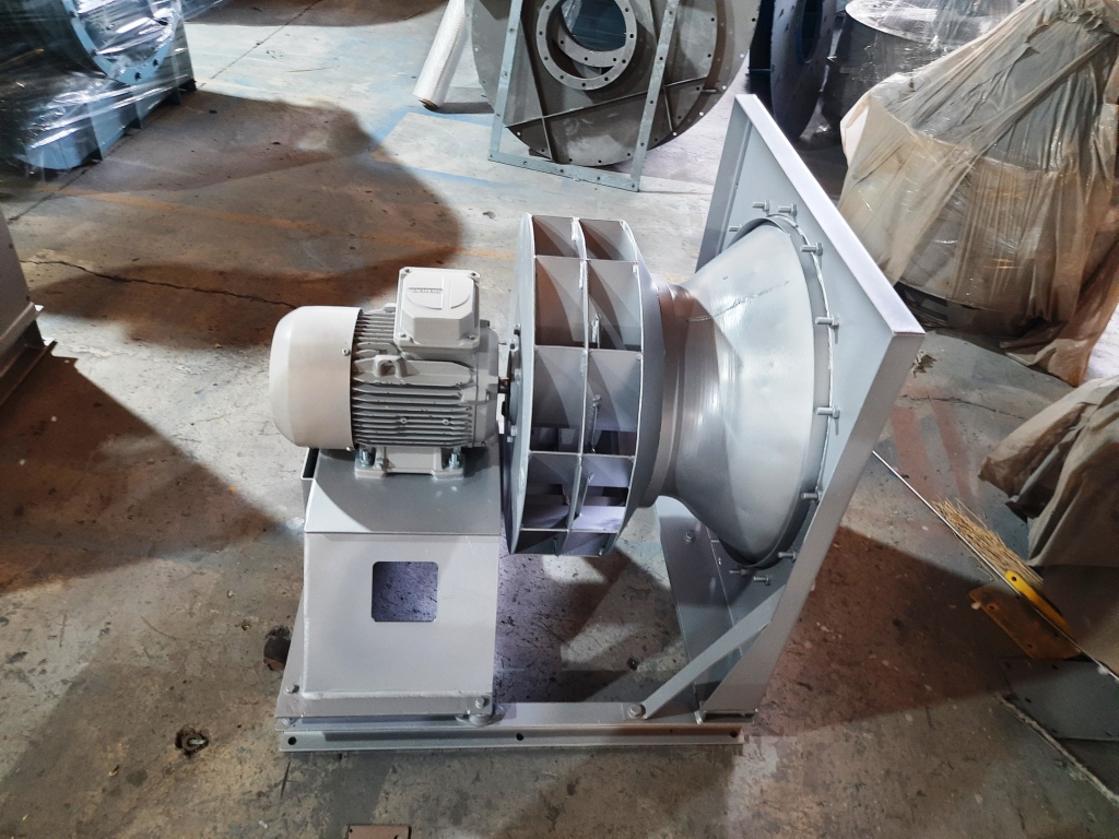
A plug/plenum fan is an unhoused impeller mounted directly on the motor shaft that discharges into the plenum section of the air-handling unit — no scroll casing. It is compact, gives a clean discharge into the AHU, and is the common choice for built-up and packaged units. A housed fan uses a conventional scroll volute and a defined discharge flange, which suits a directly ducted take-off. We supply both. Plug/plenum is our default inside an AHU; we build housed where the layout needs a ducted volute discharge, and we tell you the trade-off on the quote rather than defaulting to whichever is easier to make.
How efficient are your AHU fans, and why does it matter so much here?
We design for high static efficiency on standard duty, higher still on airfoil high-efficiency builds. It matters more on AHU duty than almost anywhere else because the fan runs near-continuously — 6,000 to 8,760 hours a year — and fan energy is the single largest electrical load in most air-handling systems. A 75 HP supply fan run several points below its best static efficiency wastes tens of MWh a year at 8,000 hours, and over a 20-year life that gap dwarfs the purchase price of the fan. We give you the offered efficiency on the quote, not a generic catalogue figure.
How do you keep the fan quiet where the AHU sits next to occupied space?
We predict sound power per octave band, select a low-tip-speed airfoil wheel that is inherently quieter, and size the attenuator scope to your room criterion. As standard we design to below 85 dB(A) at 1 m. Below 80 dB(A) is achievable with inlet and discharge silencers plus an acoustic-lagged casing; below 75 dB(A) needs an acoustic enclosure. Tell us the NC or RC target for the space and where the AHU sits relative to it, and we engineer the wheel selection and the attenuation to meet it rather than quoting a single-figure dB(A) that hides the low-frequency content.
Should I specify VFD or a discharge damper for control?
VFD is our default. AHU flow tracks occupancy and load across a wide range, and on a VAV system the unit spends most of the year well below design flow. VFD speed control is more efficient than a discharge damper across the operating range because it avoids the throttling loss at part-load, and it holds space pressure as VAV boxes open and close. On a supply/return pair we match the two drives so they turn down together. A damper remains available for a legacy retrofit where the existing motor and starter cannot take a drive.
How do supply and return fans stay balanced across turndown?
The building holds its target pressure only if the supply and return fans track each other as flow changes. We size both onto the stable, falling side of their curves so neither drifts toward stall at low flow, match the VFD drives so they turn down together on a common signal, and set the duty points so the intended supply-minus-return offset holds across the range. On a VAV system that spends most of the year at part-load, this is what keeps the space from going over- or under-pressure as boxes modulate. We document the paired duty on the GA so the balance is engineered, not left to site commissioning to rescue.
Can you build the fan for a pharma or food AHU that needs cleanable construction?
Yes. For pharma utility HVAC, food process areas and wash-down environments we build a stainless-steel wheel and a cleanable, crevice-minimised construction so the fan can be wiped down and does not trap product or moisture. Note this page covers general comfort and process HVAC; a classified cleanroom AHU — with its containment, filter-integrity and validation requirements — is a separate duty and a separate page. Tell us the hygiene standard and whether the return path is classified, and we build the material and detailing to it.
What is the lead time for a standard AHU fan?
A standard engineered AHU fan runs roughly 8 to 12 weeks order-to-dispatch: offer in 3 to 5 working days, GA drawing 2 to 3 weeks from PO, manufacture, balance and paint 5 to 8 weeks (shorter than a hot or abrasive fan because the materials are simpler and there is no wear package), and performance test plus FAT 1 week. A matched supply-and-return set, or an acoustic-enclosure build, adds a little to the schedule — we confirm a dated commitment against your AHU delivery window, not a placeholder.
Are your fans AMCA-certified, and what about CE and ATEX?
To be precise about the claims: performance is tested in-house to the AMCA 210 / ISO 5801 method on our 200 HP VFD test rig — that is testing to the AMCA method, not an AMCA certification, and Jitamitra is not an AMCA member. Every fan is dynamically balanced to ISO 21940 G6.3 as standard, with G2.5 or G1.0 on application. CE is self-declared per 2006/42/EC and 2014/35/EU, and ATEX Zone 2/22 is self-declared per 2014/34/EU (Category 3) where an AHU handles a classified return path — those are self-declarations of conformity, not third-party certifications, and ATEX Zone 2 service uses an aluminium impeller. Our only third-party certification is ISO 9001:2015.
Across the range

Where ahu supply / return fans fit — the fans that run them, related duties, and the industries served.

The same engineering, viewed three ways — by fan family, by duty, and by industry. Follow the cross-references.

Take it further

Specs an engineer can use — not a brochure.

Engineer to engineer

Send us the duty point.
We'll quote in 3 working days — always.

No model numbers needed. Give us the operating conditions — flow, static, gas temperature, composition, particulate, and any tender standard — and our application engineers size the fan and quote it. Attach a spec or GA if you have one.

+91 90110 09155  ·  mihir.jitamitra@gmail.com